56
IdeaPad Y560 Hardware Maintenance Manual
1140 Keyboard bezel, speakers, power board and volume
buttons board
For access, remove these FRUs in order:
• “1010 Battery pack” on page 35
• “1030 Hard disk drive (HDD) slot cover and HDD” on page 37
• “1050 Thermal slot cover” on page 40
• “1090 SIM card slot cover” on page 46
• “1110 PCI Express Mini Card for wireless LAN/WAN and TV card” on page 48
• “1120 Keyboard cover, system status indicator board and touch inductive
panel” on page 52
• “1130 Keyboard” on page 55
Note: Power board and volume buttons board are attached to the keyboard bezel.
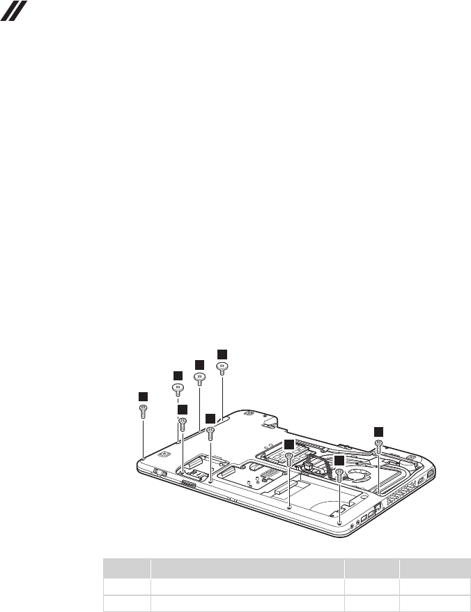
Figure 14. Removal steps of keyboard bezel, speakers, power board and
volume buttons board
Remove three screws
1
and six screws
2
on the bottom.
1
1
1
2
2
2
2
2
2
Step Screw (quantity) Color Torque
1
M2.5 × 2 mm, at-head, nylok-coated (3) Black 1.5±0.2 kgfcm
2
M2.5 × 6.5 mm, at-head, nylok-coated (6) Black 2.5±0.2 kgfcm


