Instructions for Use
10/100/1000 Mbps
5-Port Gigabit
Ethernet Switch
DI-041-47611-05A
47611-5GB
59-25 Little Neck Parkway.
Little Neck, N.Y. 11362-2591, USA
Tech Support: 800-824-3005
www.leviton.com
10/100/1000 Mbps 5-Port
Gigabit Ethernet Switch
DESCRIPTION
The 10/100/1000 Mbps 5-Port Gigabit
Ethernet Switch is used to create a small,
Local Area Network (LAN). Patch cords
connected from the Switch to structured
wiring system connects network data
devices throughout the home.
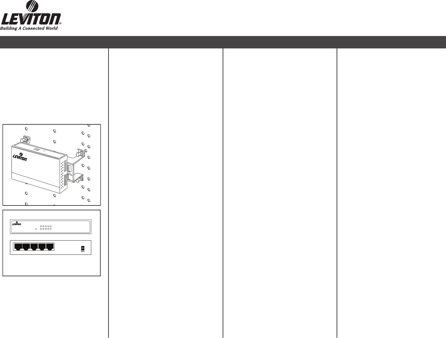
INSTALLATION
To install the module into the Leviton
Structured Media™ Center (SMC), simply
align the mounting pins with the grid holes
in the back of the SMC. With the mounting
pin plungers in the “out” position, press the
unit into the grid in the desired location.
Secure by pushing the plungers in.
(Figure 1)
Note: To remove the bracket from
the switch, loosen the screws
underneath the Switch and bracket
combination, then slide the units
apart.
Front Panel (Figure 2)
A. Power: Illuminates green when
powered up.
B. LNK/ACT LED: LINK illuminates solid
green when the port is connected to an
ethernet or fast ethernet connection.
Activity illuminates blinking green when
data is being transmitted or received.
C. 10/100/1000 LED: Illuminates green
when a 10 Mbps, 100 Mbps or 1000
Mbps connection is made.
Rear Panel (Figure 2)
A. RJ-45 Ports: Switch is equipped
with 5 RJ-45 ports, designed to make
10/100/1000 Ethernet connections.
B. Auto-detect Uplink: Use any port to
cascade additional switches, hubs or
routers.
C. Power Supply Port: Connect the
provided 12 VDC Power Supply to the
Switch.
MAKING NETWORK CONNECTIONS
10/100/1000 Mbps is a specification
for Ethernet networks based on twisted
pair cabling. The maximum length of a
segment for 10/100/1000 Mbps networks
is 100 meters. The cable and connectors
are commonly referred to as a Category
5e or greater patch cord and RJ-45
connectors, respectively.
To establish 10/100/1000 Mbps
connections, you will need the following
equipment:
• Twisted pair Category 5e or greater patch
cord for switch-to-NIC (network interface
card) connections.
• Twisted pair Category 5e or greater patch
cord for switch-to-switch connections,
usually referred to as “switch cascading”.
Note: An 10/100/1000 Mbps network
card is also required for Gigabit
operation.
Note: In order to achieve 1000 Mbps
Speed, the connected devices must
support 1000 Mbps networking
speeds.
Establishing Connections
1. Ensure that both the Switch and the
soon-to-be connected device are in the
POWER OFF mode.
2. Plug one end of a patch cord into an
available 10/100/1000 Mbps Switch
port. Connect that cord’s other end to
the intended port in a Category 5e or
greater Voice & Data Module which is
already wired to the wall location.
3. Connect a patch cord from the NIC to
the soon-to-be connected device at the
wall location to complete the link.
Uplinking (Cascading) to Other
Switches and Hubs
Switches, hubs and similar network
devices are uplinked to the switch with
straight-through Category 5e cabling.
1. Connect a Category 5e cable from the
Uplink port on your network device to
any port on the Switch.
Note: 1000 Mbps is only supported in
Category 5e or greater cables.
FCC STATEMENT
This equipment has been tested and found
to comply with the limits for a Class B
digital device, pursuant to part 15 of the
FCC Rules. These limits are designed
to provide reasonable protection against
harmful interference in a residential
installation. This equipment generates,
uses and can radiate radio frequency
energy and, if not installed and used in
accordance with the instructions, may
cause harmful interference to radio
communications. However, there is no
guarantee that interference will not occur
in a particular installation. If this equipment
does cause harmful interference to radio
or television reception, which can be
determined by turning the equipment off
and on, the user is encouraged to try to
correct the interference by one or more of
the following measures:
Reorient or relocate the receiving antenna.
• Increase the separation between the
equipment and receiver.
• Connect the equipment into an outlet on
a circuit different from that to which the
receiver is connected.
• Consult the dealer or an experienced
radio/TV technician for help.
1
1234
5
12 VDC
5-Port Rear Panel
+
1
2
3
4
5
LNK/ACT
POWER
100
5-Port Front Panel
10/100/1000 Mbps 5-port
Gigabit Ethernet Switch
2
10
/
100
Mb
p
s 5-Port Et
hern
et Switc
h
1
P
O
W
E
R
1
10/1
0
0
/1000 Mbp
s
5-
Po
r
t
Gi
g
a
bit
E
t
he
r
n
e
t
Sw
it
ch


