1
NOTE: This module must be “included in the Network” only where it will be permanently installed. The proper operation of this node in the
mesh network is dependent on it knowing its location with respect to other nodes. You cannot “test bench” confi gure this module.
WS15Z-1 WALL MOUNTED SWITCH
Linear’s family of Z-Wave certifi ed wireless lighting controls (switches,
dimmers, outlets and plug-in modules) brings a new level of intelligent
wireless capability to commercial and residential environments.
The Z-Wave wireless protocol is an international wireless standard for
remote home automation, security and other applications. Embedded in
each device, the Z-Wave smart chip enables two-way RF communication
among hundreds of Z-Wave enabled devices, allowing products and
services from multiple manufacturers to work seamlessly.
Linear Z-Wave products are easy to install, and allow dealers to create
an integrated wireless network with nearly limitless expansion and
interoperability with security and health monitoring systems, energy
management, home entertainment, appliances, and more.
DANGER! SHOCK HAZARD. Read and understand these
instructions before installing. This device is intended for installation in
accordance with the National Electric code and local regulations in the
United States, or the Canadian Electrical Code and local regulations
in Canada. It is recommended that a qualifi ed electrician perform this
installation. Make sure the load controlled by the switch does not exceed
1800 watts. For indoor use only. Retain instructions for future use.
INSTALLATION
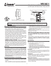
Wire this Switch in place of a current wall switch according to the diagram
above. When used, WT00Z-1’s are required to be wired to the same
line (or neutral) which is also wired to the master unit as well as the
load being controlled, and not wired to any other neutral. If multiple
neutrals are tied together in one box, separate the neutrals to preserve
the integrity of the WS15Z-1 circuit. Caution! Do not wire unit “live” (with
power on the circuit) and do not allow the yellow wire to contact line
voltage, neutral or ground or you will damage the device. Refer to your
Controller operating instructions to add this module under the command
of the Wireless Controller.
INCLUDING/EXCLUDING WS15Z-1 TO THE NETWORK
STEP 1. Prepare the Controller to include a unit to the network by adding
it to a group (method of adding a node to the network). Refer to controller
instructions.
STEP 2. The WS15Z-1 must be in its permanently installed location.
• To add a node: NWI: Tap the button once. This can be done upon
power-up of the node to be included, or once the controller is prepared
to add all nodes to the network. Classic inclusion: Tap the button twice
• To remove a node: Tap the button twice
STEP 3. You should see an indication on your Controller that the “device
was included” in the network.
NOTE: If you have trouble adding the WS15Z-1 to a group it may be
that the Home ID and Node ID were not cleared from it after testing.
You must fi rst “RESET UNIT” with your controller to remove it from
the network.
Although adding it to a group includes it in the network, removing it from
a group does not remove it from the network. If removed from a group,
it functions as a repeater (only). “RESET UNIT” removes it completely
from the network.
BASIC OPERATION
(Local Control)
The switch paddle on the WS15Z-1 allows the user to:
• Turn the attached load on or off.
• Tapping top of switch turns the load attached ON.
• Tapping bottom of switch turns the load attached OFF.
• Pressing and holding switch does not effect the load attached to the
WS15Z-1, but will allow dimming and brightening of Z-Wave dimmers
if associated (see below for details)
LED Indication
The LED on the WS15Z-1 will turn ON when the load attached is OFF, to
act as a night light. However, the LED can be user confi gured to turn ON,
when the load attached is ON, if so desired.
Remote Control
The WS15Z-1 will respond to BASIC and BINARY commands that are
part of the Z-Wave system. Refer to your controller’s instructions as to
whether your controller can transmit those commands.
Internal Circuit Protection
The WS15Z-1 internal circuitry is protected by an internal fuse. This
internal fuse is factory serviceable only. Check your home circuit breakers
before concluding that the product must be returned to manufacturer for
repair at a nominal charge.
WS15Z-1
Z-Wave Radio Frequency (RF) Controlled, 120 VAC, Scene
and NWI Capable, Wall Mounted Switch, 3-Way, Series 300
NEUTRAL
120 VAC
PUSH ON
WHITE
LINE
BLACK
PUSH OFF
STATUS LED
GREEN
GROUND
PUSH TOP OR
BOTTOM OF PADDLE
SWITCH TO CONFIGURE
SCORED TAB WILL
BREAK FLUSH WITH
EDGE OF PLASTIC
BLUE
LOAD
15 AMPS
MAXIMUM
WS15Z-1 AND THE LOAD MUST SHARE THE SAME PROPRIETARY NEUTRAL
Shown with supplied decorative trim plate