Contents
Contents
i
86-172010-00 C05
section description . . . . . . . . . . . . . . . . . . . . . . . . . . . . . . . . . . . . . . . . . . .page
Revision History . . . . . . . . . . . . . . . . . . . . . . . . . . . . . . . . . . . . . . . . . .ii
IMPORTANT SAFETY INSTRUCTIONS . . . . . . . . . . . . . . . . . . . . . . .v
Safety of Persons . . . . . . . . . . . . . . . . . . . . . . . . . . . . . . . . . . . . . . . .vii
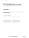
CAUTION: Record All Serial Numbers! . . . . . . . . . . . . . . . . . . . . . . .viii
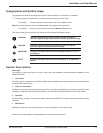
Typographical and Symbol Usage . . . . . . . . . . . . . . . . . . . . . . . . . . . .ix
Section Descriptions . . . . . . . . . . . . . . . . . . . . . . . . . . . . . . . . . . . . . .ix
Quick Start
Getting Started with Galaxy 3000 . . . . . . . . . . . . . . . . . . . . . . . . . . . . . . . . . . .QS—1
First steps by an on-site qualified Technical Engineer . . . . . . . . . . . . . . . . . . .QS—1
Final steps by MGE Field Service Engineer . . . . . . . . . . . . . . . . . . . . . . . . . . . .QS—1
Required Equipment and Tools . . . . . . . . . . . . . . . . . . . . . . . . . . . . . . . . . . . . .QS—1
STEP 1 Unpacking and Positioning . . . . . . . . . . . . . . . . . . . . . . . . . .QS—2
STEP 2 Connect the Main Utility Power . . . . . . . . . . . . . . . . . . . . . .QS—3
STEP 3 Connect the Output to the Distribution Panel (Load) . . . . . .QS—4
STEP 4 Call MGE UPS Systems for Field Engineer Service . . . . . .QS—4
STEP 5 Arrival of MGE Field Engineer . . . . . . . . . . . . . . . . . . . . . . .QS—4
Operator Interface Panel . . . . . . . . . . . . . . . . . . . . . . . . . . . . . . . . . . . . . . . . . .QS—5
Quick Start Notes . . . . . . . . . . . . . . . . . . . . . . . . . . . . . . . . . . . . . . . . . . . . . . . .QS—6
Section 1 Introduction
1.0 Scope . . . . . . . . . . . . . . . . . . . . . . . . . . . . . . . . . . . . . . . . . . . . . .1 — 1
1.1 General Description . . . . . . . . . . . . . . . . . . . . . . . . . . . . . . . . . . .1 — 1
1.1.1 Major Components . . . . . . . . . . . . . . . . . . . . . . . . . . . . . . . . . . . .1 — 2
1.1.2 Galaxy 3000 Micro and Standard Cabinets . . . . . . . . . . . . . . . . .1 — 2
1.1.3 Preparation for Operation . . . . . . . . . . . . . . . . . . . . . . . . . . . . . . .1 — 2
1.1.4 Cabinet Descriptions and Placement . . . . . . . . . . . . . . . . . . . . . .1 — 3
1.1.5 Cabinet Clearance and Environmental Requirements . . . . . . . . .1 — 3
1.1.5.1 Air Flow / Heat Rejection . . . . . . . . . . . . . . . . . . . . . . . .1 — 3
1.1.5.2 Recommended Operating Environments . . . . . . . . . . . .1 — 3
1.2 Cabinet Footprints and Electrical Entries . . . . . . . . . . . . . . . . . . .1 — 5
1.2.1 Conduit Plate Locations (top entry) . . . . . . . . . . . . . . . . . . . . . . .1 — 5
1.2.2 Conduit Plate Locations (bottom entry) . . . . . . . . . . . . . . . . . . . .1 — 5
1.2.3 Single Line Diagram . . . . . . . . . . . . . . . . . . . . . . . . . . . . . . . . . . .1 — 6
1.3 Preparation for Storage . . . . . . . . . . . . . . . . . . . . . . . . . . . . . . . .1 — 6


