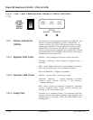
Selection of the AC output voltage is accomplished by
moving a connector plug. The printed circuit board has a 10
pin connector (J3) and its mate is a 9 pin plug (P3). Moving
this plug to the left (rear) position selects the 120VAC
position (100, 110, 115, 120 VAC). Moving of the plug to the
right (toward the front panel) connects the inverter to produce
240VAC (200, 220, 230, or 240VAC).
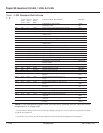
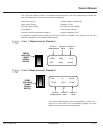
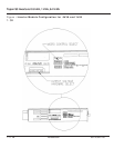
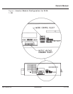
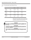
An eight position DIP switch can be seen through the access
hole in the left side of the inverter module. The switches are
labeled "MICRO CONTROL SELECT". The switch functions
are clearly labeled. Switch positions 1 and 2 are reserved
and should be set to the OFF position. Switch position 3 is
ON when no BYPASS option is installed, OFF when the
BYPASS option is installed. Switch position 4 is OFF if AUTO
RESTART is desired, ON if manual restart is desired. Switch
position 5 & 6 select the output voltage of the inverter.
Switches 5 & 6 OFF = 120 or 240 VAC output, 5 ON & 6
OFF = 115 or 230 VAC output, 5 OFF & 6 ON = 110 or 220
VAC output, 5 ON & 6 ON = 100 or 200 VAC. See Figure 1-3.
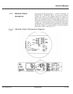
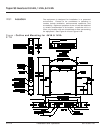
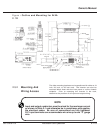
The inverter assembly consists of an inverter module which
slides into the receiver cabinet. The receiver cabinet consists
of a left and right side "U" channel and a rear housing which
contains EMI filters, Maintenance bypass relay, Alarm relays,
and wire termination points. The inverter module is an easily
removable module which is secured into the receiver cabinet
via two thumb screws. All input and output power and signal
wires go through a single multi-pin connector located on the
rear of the inverter module. See Figures 2-1 and 2-2.
1.7 Mechanical
Specifications
1.6.5.2 Micro-Processor
“DIP” Switch
Settings
WARNING
Modules with "BYPASS" option installed may be damaged when utility
voltage and inverter output voltage settings are not the same.
ATTENTION
Un module avec l'option "BYPASS" risque d'être endommagé si les
réglages de tension du réseau et de sortie onduleur ne sont pas les
mêmes.
WARNUNG!
Nach Installation des "BYPASS" muss die Spannung dieselbe sein wie
die Inverter Ausgangsspannung, ansonsten Beschaedigung des
Inverter Module.
1.6.5.1 Output Voltage
Selection
1 — 14 Introduction 86-153061-00
Topaz S3 Inverters 0.5 kVA, 1 kVA, & 2 kVA


