


www.minicom.com
International HQ
Jerusalem, Israel
Tel: + 972 2 535 9666
minicom@minicom.com
North American HQ
Linden, NJ, USA
Tel: + 1 908 486 2100
info.usa@minicom.com
Customer support - support@minicom.com
5UM20094 V1.8 4/09
Universal Phantom Manager
Quick Installation Guide
UNIVERSAL PHANTOM MANAGER
1
1. What is the Phantom system?
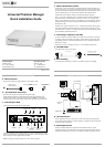
The Phantom system from Minicom is a distributed KVM switching solution for 1
or more users. In the 1-User system a Manager controls the remote computers that
are connected to Phantom Remote units. The Remote units can be either PCI cards
or boxes called Specters. For multi-user functionality add a Phantom MX II.
The Phantom system supports mixed type and multi-platform computers.
In the 1-User system, shielded CAT5 FTP cables connect the Phantom Manager to
the nearest Remote, and that Remote to the next one, and so on, in a daisy chain
pattern. The last Remote can be up to 110m/360ft away from the Manager. See the
configuration diagram on page 4 showing both Remote PCI cards and Specters in
the Phantom system.
The Multi-User system connects in a loop – as explained in Phantom MX II guide.
This Quick Installation Guide illustrates the Universal Phantom Manager (UPM)
and explains how to install it. For further information please see the softcopy Guide
on the Marketing & Documentation CD.
2. Connecting a computer to the UPM
To run the Phantom system the UPM does not need to be connected to a computer.
A computer must be connected to the UPM to perform Phantom applications such
as upgrading firmware or renumbering Remote units. This is discussed in detail in
softcopy User Guide.
When you do connect a computer use the 3 in 1 CPU cable illustrated below.
3. The UPM cables
The cables below connect to the UPM.
Shielded CAT5 FTP cable
(Supplied with the Remote units)
3 in 1 CPU cable
4. Rack mounting
The UPM is rack mountable. To obtain a 19” bracket, order P/N 5AC00202.
QUICK INSTALLATION GUIDE
2
5. UPM accessories
The accessories below are explained fully in the softcopy Guide.
RS232 serial cable -
For Phantom applications
In Line Coupler -
To bypass Remote units
Terminator -
Connects to last Remote in daisy chain
6. Pre-installation instructions
Disconnect all computers from the electrical power supply.
Cables should be placed away from fluorescent lights, air conditioners, and
machines that are likely to generate electrical noise. Caution: For continued
protection against risk of fire, replace with the same type and rating of fuse only.
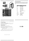
7. Connecting the UPM
The figure below illustrates the rear of the UPM.
Mouse
In port
Terminal
port
System
Out port
RS232
port
Power
LED
Power
connector
www.minicom.com
USER COMPUTER
SYSTEMSERVICEPOWER
85-265VAC 50/60 Hz
Keyboard
Out port
Mouse
Out port
Keyboard
In port
Video
In port
Video
Out port
Connect a keyboard, monitor, mouse plus the 3 in 1 CPU cable and Power cord to
the UPM and computer as illustrated in the figure below. Connect the Power cord.
Only use the power cord supplied with the UPM.
Note! Connecting a computer and the 3 in 1 CPU cable is optional.
UNIVERSAL PHANTOM MANAGER
3
To computer's
Keyboard port
To computer's
Mouse port
To
computer's
Video port
3 in 1 CPU cable
SD
P110
www.minicom.com
USER COMPUTER
SYSTEMSERVICEPOWER
85-265VAC 50/60 Hz
To
System
port
To Phantom Remote
System In port
Shielded CAT5
FTP cable
UPM
8. The Terminal port
When using RS232 servers in the system, you have the option of operating these
servers through the computer’s Terminal emulation or through an optional terminal
connected to the Terminal port.
9. What happens next?
Install the Phantom Remotes as explained in The Phantom Remote – Quick
Installation Guide. Give the Remotes ID numbers and configure keyboard settings
explained in the Read This First (RTF). The Phantom system is then ready for use.