


Technical support - support@minicom.com
© 2009 Copyright Minicom Advanced Systems. All rights reserved.
5UM60000 V1.2 9/09
DX User IP II - Quick Start Guide
1. Introduction
To take advantage of the DX User IP II full range of features, we recommend you
read the softcopy User Guide after performing the Quick Start procedure. It’s in
PDF format on the supplied CD or on our website www.minicom.com in the
Support section.
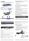
Figure 1 illustrates the basic configuration of the DX system with the DX User IP II
and DX Users connected to peripheral devices via the DX Central.
DX 432 Central
X-RICC
X-RICC
X-RICC
1 32
Computer
To computers
Computer
Power Link
MINICOM
DX432
Central
Local
User
MINICO M
Power
DX
User
DX User
Computer
DX User IP II
Local
User
MINICOM
SystemOKActivity
DXU-IP
II
Internet / VPN / LAN
Remote
User
Figure 1 DX User IP II usage scenario
DX USER IP II
1
1.1 Standalone mode or KVM.net
DX User IP II can be used in any of the following 3 modes:
· Standalone
· KVM.net enabled
· KVM.net managed
KVM.net is a centralized IP based system for secure control of servers and network
devices, power and user administration in the data center environment. KVM.net
combines Out-Of-Band, KVM via IP access with modern IT standards and
requirements. It is the most comprehensive remote server maintenance solution
available in the market today.
These 3 modes are now explained.
1.1.1 Standalone mode
Standalone mode refers to using the DX User IP II as part of the DX system only
and working via the DX AIM interface without KVM.net, for remote KVM access
and control via a LAN or Internet connection.
1.1.2 KVM.net enabled / managed
The DX User IP II can be KVM.net enabled or KVM.net managed. Both of these
refer to managing and accessing servers connected to the DX system via the
KVM.net Manager.
KVM.net enabled means the DX is still capable of working in Standalone mode.
KVM.net managed means the DX is fully managed and controlled by KVM.net,
access to the AIM interface is blocked but can be achieved where necessary via
hotkeys. Details of the differences between KVM.net enabled and managed will be
explained in the configuration and operating sections later on in this Guide.
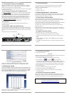
2. DX User IP II front panel
Figure 2 illustrates the DX User IP II front panel.
MINICOM
System OKActivity
DXU - IP
II
Figure 2 Front panel
The table below explains the functions of the front panel LEDs.
QUICK START GUIDE
2
LED Function
Activity LED solid when a remote user operates the DXU IP II
System OK LED solid when DX User IP II connected and functioning
2.1 DX User IP II rear panel
Figure 3 illustrates the rear panel of the DX User IP II.
Power
connector
RS232 Serial
port
POWER
100-240 VAC 50/60 Hz
ww w.minicom .com
Go Lock
button
Ethernet
port
ETHERNET
SERIAL
I
0
SYSTEM
Keyboard
Mouse
Monitor
USB TERMINAL
USER
USB
ports
RS232
Terminal port
CAT5 to DX
Central
GO LOCK
DX Reset
button
SERIAL 2
Serial 2
port
Figure 3 DX User IP II rear panel ports
DX Reset button
The DX Reset button resets the DX parts of the DX User IP II.
Go Lock button
The Go Lock button disconnects the active remote session and returns control to the
local user.
Serial / Serial 2 port
The Serial port is only used for KVM.net managed mode when the DX User IP II is
the Master Console – (explained in the softcopy User Guide).
In Standalone and KVM.net enable modes, the Serial 2 port can be used for any
RS232 application, e.g. managing a router or power switch.
Terminal port
In Standalone and KVM.net enable modes only, when there are X-RICC RS232s in
the DX system, you can control them locally through an RS232 terminal connected
to the DX User IP II.
Ethernet - Connects the DX User IP II to an Ethernet network.
DX USER IP II
3
USB ports
Update the DXU firmware via a Minicom Flash USB key. See the DX User Guide
for information on updating firmware.
System port – Used to connect the DX User IP II to the DX Central.
KVM ports – Used for optional local console.
3. Pre-installation guidelines
· Place cables away from fluorescent lights, air conditioners, and machines that
are likely to generate electrical noise
· The maximum distance between each device (computer, KVM switch or second
level DX Central) and the DX Central is 100m/330ft. The maximum distance
between the DX Central and the DX User IP II is also 100m/330ft. For best
performance place the DXU IP II as close as possible to the DX Central.
4. Connecting the DX User IP II
Figure 4 below illustrates the connections of the DX User IP to the DX system. See
below for more details.
POWER
100-240 VAC 50/60 Hz
www.minicom.com
ETHERNET
SERIAL
I
0
SYSTEM
USB TERMINAL
USER
GO LOCK
SERIAL 2
SD
P110
CAT5
cable
To DX Central
User port
Internet / VPN / LAN
Remote user
(Optional)
Local
User
console
Figure 4 DX User IP connections