21
Operation Mode Setting of the Inverter
2
FUNCTIONS
2.5 Operation Mode Setting of the Inverter
2.5.1 Operation mode setting
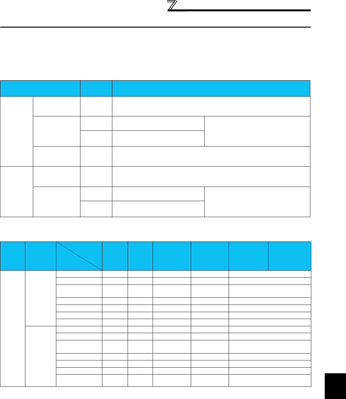
For operating the inverter using FR Configurator (parameter change, auto tuning and test operation, etc.), the operation mode
of inverter must be set. Refer to the table, and select an operation mode, which matches to each connecting method. The
selection of operation mode can be made using the tool bar. (Refer to page 18)
* When connecting a USB connector, set "3" in Pr.551 PU mode control source selection. The change for the setting value of Pr.551 becomes valid when turning on
the power next time or resetting the inverter.
Controllability through communcation
Connecting method
Operation
mode*
Parameter setting
Direct
connection
with FR
Configurator
and the
Inverter
PU connector
(RS-485
connector)
PU
Pr. 122 PU communication check time interval
≠
0 (Factory setting = 9999)
Pr. 123 PU communication waiting time setting
= 9999 (Factory setting)
RS-485 terminal
PU
Pr. 551 PU mode control source selection
= 2
(Factory setting)
Pr. 336 RS-485 communication check time
interval
≠
0
Pr. 337 RS-485 communication waiting time
setting
= 9999 (Factory setting)
LINK Pr. 551 PU mode control source selection
= 1
USB connector
(FR-A700
series only)
PU
Pr. 548 USB communication check time interval
≠
0 (Factory setting = 9999)
Pr. 551 PU mode control source selection
= 3
Connection
via GOT
PU connector
(RS-485
connector)
PU
Pr. 123 PU communication waiting time setting
= 0
Pr. 551 PU mode control source selection
= 2 (Factory setting)
RS-485 terminal
PU
Pr. 551 PU mode control source selection
= 2
(Factory setting)
Pr. 336 RS-485 communication check time
interval
≠
0
Pr. 337 RS-485 communication waiting time
setting
= 0
LINK Pr. 551 PU mode control source selection
= 1
Operation
Location
Condition
(Pr. 551
Setting)
Operation
Mode
Item
PU
Operation
External
Operation
External/PU
Combined
Operation Mode
1
(
Pr. 79
= 3)
External/PU
Combined
Operation
Mode 2
(Pr. 79 = 4)
NET Operation
(when RS-485
terminals are
used)
*6
NET Operation
(when
communication
option is used)
*7
Control by RS-485 communication from PU connector
2
(PU
connector)
Run command (start)
{ ×× { ×
Run command (stop)
{ *3 *3 { *3
Running frequency
setting
{ × { ××
Monitor {{ { { {
Parameter write { *4 × *5 { *4 { *4 × *5
Parameter read {{ { { {
Inverter reset {{ { { {
Except for 2
Run command (start)
×× × × ×
Run command (stop)
*3 *3 *3 *3 *3
Running frequency
setting
×× × × ×
Monitor {{ { { {
Parameter write ×
*5 × *5 × *5 × *5 × *5
Parameter read {{ { { {
Inverter reset {{ { { {


