23
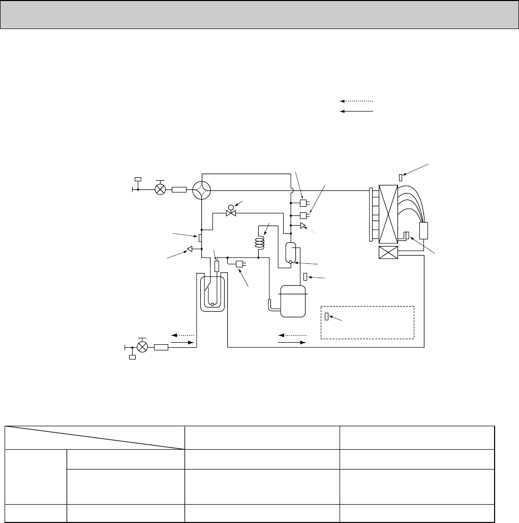
8-2. REFRIGERANT SYSTEM DIAGRAM
PUMY-P100VHM PUMY-P125VHM PUMY-P140VHM
PUMY-P100VHMA PUMY-P125VHMA PUMY-P140VHMA
Refrigerant Gas pipe
<5/8>
Refrigerant Liquid pipe
<3/8>
Check valve <Low pressure>
Accumulator
Thermistor <Low pressure saturation
temperature> (TH6)
Bypass
valve (SV1)
Capillary tube
Check valve
<High pressure>
High pressure sensor
(63HS)
High pressure
switch (63H)
Low pressure
switch (63L)
Thermistor (TH7)
(Outdoor temperature)
Discharge
thermistor (TH4)
Heatsink
thermistor (TH8)
Thermistor (TH3)
(Pipe temperature)
Oil separator
Service port
Service
port
4-way valve
Strainer
Strainer
Strainer
Stop valve
Stop valve
Distributor
Compressor
Strainer
Refrigerant flow in cooling
Refrigerant flow in heating
Refrigerant piping specifications <dimensions of flared connector>
Capillary tube for oil separator : [2.5 o [0.8 o L1000
Capacity
Item
Liquid piping
Gas piping
P15, P20, P25, P32, P40, P50
P63, P80, P100
P125, P140
P100, P125, P140
Indoor unit
Outdoor unit
[6.35<1/4>
[9.52<3/8>
[9.52<3/8>
[12.7<1/2>
[15.88<5/8>
[15.88<5/8>
Unit:mm<inch>
OC376B--1.qxp 08.1.17 1:14 PM Page 23


