


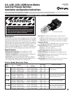
LLS, LLSB, LLSR, LLSRB Series Models
Lead Line Pressure Switches
Installation and Operation Instructions
LLS-93096N
Effective 03-94
Section 05
Description
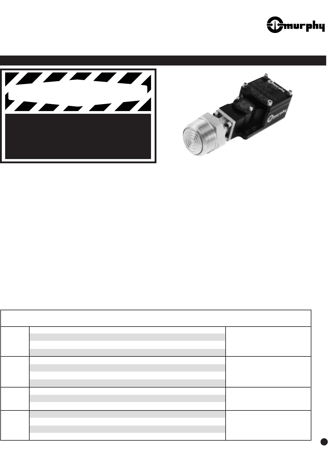
The LLS Series is a pressure switch for applications where viscous liquids
could plug the sensing orifice. LLS and LLSB models have a 2 inch NPT
male connection which attaches directly into the process line. LLSR and
LLSRB models feature a remote sensor connected to the pressure switch by a
length of stainless steel capillary and armor. The snap-acting switch is field
adjustable. The switch is housed in a hard anodized aluminum enclosure.
Optional for LLSR and LLSRB models is a 1 inch NPT x 1 inch NPT (male)
pulsation dampener to minimize damaging pressure pulsation to the switch.
Specifications
• Maximum Ambient Temperature: -10° to +160°F (-23° to +71°C).
• Maximum Process Temperature: -40° to +160°F (-40° to +71°C).
• Temperature Compensation: The volumetric expansion and contraction of
the fill may cause a shift of ±3% to ±5% of the set point.
• Switch Enclosure: Aluminum hard anodized (black). NEMA 4, 4x. NEMA 7
and 9 explosion-proof, waterproof and corrosion resistant. Suitable for Class I,
Div. 1, Groups A, B, C, D; Class II, Div. 2, Groups E, F, G.
• Sensor Body: LLS: CRS steel chromate plated; 2 in. NPT connection.
LLSB: Thick wall 304 stainless steel sensor 2 in. NPT process connection.
LLSR: Remote Sensor; Nickel plated steel, stainless steel capillary.
LLSRB: Remote Sensor; 316 stainless steel housing and capillary.
• Diaphragm Materials:
LLS/LLSB: Ni-SPAN
®
. LLSR/LLSRB: 316L S. Steel–Teflon* coated.
• Snap-switch Ratings: SPDT (Std.): 15 A @ 125, 250 or 480 VAC
SPDT (Gold): 100 mA @ 125 VAC; 0.250 A @ 6 VDC
DPDT (Std.): 11 A @ 125 or 250 VAC
DPDT (Gold): 100 mA @ 125 VAC; 0.250 A @ 6 VDC
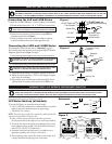
• Trip Point Adjustment: Field-adjusted with screwdriver.
• LLSR/LLSRB Mount: 4-hole bolt pattern; 1/4 in. (6 mm) dia. bolts.
• LLS/LLSB Mount: Direct mount into process (2 in. NPT connection).
• Shipping Weight: LLS/LLSB: 4 lbs. 9 oz. (2.25 kg).
LLSR/LLSRB: 7 lbs. 12 oz. (3.23 kg).
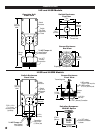
• Shipping Dimensions: LLS/LLSB: 10 x 9-1/4 x 5-3/4 in. (254 x 235 x 146 mm).
LLSR/LLSRB: 15-3/4 x 11 x 5-1/4 in. (400 x 279 x 133 mm).
Please read the following information before installing. A visual inspection of this product for damage during shipping is recommended before mounting.
It is your responsibility to have a qualified person install the unit and make sure installation conforms to NEC and local codes.
GENERAL INFORMATION
1
®
FRANK W.
MFR.
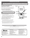
WARNING
BEFORE BEGINNING INSTALLATION OF THIS MURPHY PRODUCT
✔ Disconnect all electrical power to the machine.
✔ Make sure the machine cannot operate during installation.
✔ Follow all safety warnings of the machine manufacturer.
✔ Read and follow all installation instructions.
LLS Series Pressure Switch
Sensor Model Selection Table
Base
Model
Switch Adjustment Range
Dead Band Approximate
Max System
Wetted Parts Materials
100–1750 689 kPa–12 MPa 15–100 103 kPa–689 kPa 2500 17.2
200–2500 13.8 MPa–17.2 MPa 20–150 137 kPa–1.03 MPa 3000 20.6
400–4000 2.8 MPa–27.5 MPa 75–450 517 kPa–3.1 MPa 5000 34.4
100–1750 689 kPa–12 MPa 15–100 103 kPa–689 kPa 2500 17.2
200–2500 13.8 MPa–17.2 MPa 20–150 137 kPa–1.03 MPa 3000 20.6
400–4000 2.8 MPa–27.5 MPa 75–450 517 kPa–3.1 MPa 5000 34.4
CRS steel sensor –chromate plated (yellow)
Ni-SPAN
®
diaphragm.
Thick wall 304 stainless steel sensor housing;
Ni-SPAN
®
diaphragm. Meets NACE MR-01-75
standard for direct exposure to H
2
S.
LLS
LLSB
100–1750 689 kPa–12 MPa 15–100 103 kPa–689 kPa 2500 17.2
100–1750 689 kPa–12 MPa 15–100 103 kPa–689 kPa 2500 17.2
200–2500 13.8 MPa–17.2 MPa 20–100 137 kPa–689 kPa 3000 20.6
50–450 345 kPa–3.1 MPa 5–45 34 kPa–310 kPa 1500 10.3
Remote sensor–Nickel plated steel w/ stainless
steel capillary; Teflon* coated diaphragm.
LLSR
200–2500 13.8 MPa–17.2 MPa 20–150 137 kPa–1.03 MPa 5000 34.4
400–4000 2.8 MPa–27.5 MPa 75–450 517 kPa–3.1 MPa 5000 34.4
Remote sensor–AISI 316 stainless steel housing;
stainless steel capillary and armor; AISI 316L
stainless steel Teflon* coated diaphragm.
LLSRB
psi kPa/MPa
psi kPa/MPa psi MPa
* Teflon–DuPont Trademark
50–450 345 kPa–3.1 MPa 5–45 34 kPa–310 kPa 1500 10.3
50–450 345 kPa–3.1 MPa 5–45 34 kPa–310 kPa 1500 10.3
50–450 345 kPa–3.1 MPa 5–45 34 kPa–310 kPa 1500 10.3