38 CHAPTER 2. OVERVIEW OF THE UNDERLYING THEORY
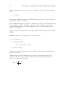
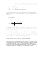
L
∞
= −Y
∞
C
T
2
Z
∞
=(I−γ
−2
Y
∞
X
∞
)
−1
ˆ
A
∞
=A+γ
−2
B
1
B
T
1
X
∞
+B
2
F
∞
+Z
∞
L
∞
C
2
.
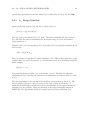
Actually, the above formulation can be used to parametrize all stabilizing controllers
which satisfy, G(s)
∞
<γ. This can be expressed as an LFT. All such controllers are
given by,
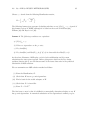
K
∞
= F
l
(M
∞
,Q),
where,
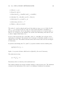
M
∞
=
ˆ
A
∞
−Z
∞
L
∞
Z
∞
B
2
F
∞
−C
2
0 I
I 0
,
and Q satisfies: Q ∈RH
∞
,Q
∞
<γ.NotethatifQ= 0 we get back the controller
given in Theorem 3. This controller is referred to as the central controller and it is the
controller calculated by the software.
Note also that the controller given above satisfies G
∞
<γ. It is not necessarily the
controller that minimizes G
∞
and is therefore referred to as a suboptimal H
∞
controller. In practice this is not a problem, and may even be an advantage. The optimal
H
∞
controller has properties which may not be desirable from an implementation point
of view. One typical property is that the high frequency gain is often large. Suboptimal
central controllers seem to be less likely to exhibit this characteristic.
2.3.5 Further Notes on the H
∞
Design Algorithm
Now that we have covered the problem solution we can look at the areas that might give
potential numerical problems. The above results give a means of calculating a controller
(if one exists) for a specified γ value. As we mentioned earlier, the smallest such γ is
referred to as γ
opt
. An iterative algorithm is used to find γ close to γ
opt
and calculate
the resulting controller. The algorithm can be stated conceptually as follows:


