2.5. µ SYNTHESIS AND D-K ITERATION 61
dynamic system. This requires fitting an approximation to the upper bound D-scale in
the iteration. We will now look at this issue more closely.
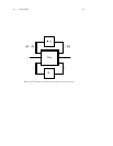
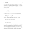
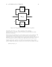
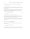
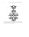
The D-K iteration procedure is illustrated schematically in Figure 2.12. It can be
summarized as follows:
i) Initialize procedure with K
0
(s): H
∞
(or other) controller for P(s).
ii) Calculate resulting closed loop: F
l
(P(s),K(s)).
iii) Calculate D scales for µ upper bound:
inf
D(ω)∈D
σ
max
[D(ω)F
l
(P(s),K(s))D(ω)
−1
].
iv) Approximate frequency data, D(ω), by
ˆ
D(s) ∈RH
∞
,with
ˆ
D(ω) ≈ D(ω).
v)DesignH
∞
controller for
ˆ
D(s)P(s)
ˆ
D
−1
(s).
vi) Gotostepii).
We have used the notation D(ω) to emphasize that the D scale arises from frequency by
frequency µ analyses of G(ω)=F
l
(P(ω),K(ω)) and is therefore a function of ω.Note
that it is NOT the frequency response of some transfer function and therefore we do
NOT use the notation D(ω).
The µ analysis of the closed loop system is unaffected by the D-scales. However the H
∞
design problem is strongly affected by scaling. The procedure aims at finding at D such
that the upper bound for the closed loop system is a close approximation to µ for the
closed loop system. There are several details about this procedure that will now be
clarified.
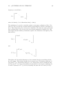
At each frequency, a scaling matrix, D(ω), can be found such that
σ
max
(D(ω)G(ω)D(ω)
−1
) is a close upper bound to µ(G(ω)) (Figure 2.12c). The D
scale is block diagonal and the block corresponding to the e and w signals can be chosen
to be the identity. The part of D corresponding to the z signal commutes with ∆ and
cancels out the part of D
−1
corresponding to the v signal. To illustrate this, consider
the D scale that might result from a block structure with only m full blocks. At each


