e
d
c
b
25
26
1
2
4
6
8
10
12
3
5
7
9
11
13
14
16
18
20
22
24
15
17
19
21
23
25
26
28
30
31
33
35
27
29
31
33
35
37
38
40
42
44
46
48
39
41
43
45
47
Status
PWR
Speed
Link/Act
Reset
PoE
Steps 1 3
Before you
start
Steps 4 7
Mounting Options
Steps 10 16
Initial Access and
Configuration
Steps 8 9
Powering Up
BES100/200
Business Ethernet Switch 100/200 Series
Quick Install Guide
All documents referenced in this Quick
Installation Guide can be downloaded at
www.nortel.com.
13
12
11
10
9
8
1
3
4
5
6
2
7
14
15
16
100
200
100
200
1. Confirm that you have the tools and package
contents as follows:
Tools Required:
a. Phillips #2 screwdriver
Package Contents:
b. BES100 or BES200 series Switch
c. Rack-mounting hardware
• Rack-mount brackets (2)
• Screws for attaching brackets to the
switch (8)
• Screws for attaching the switch to the
equipment rack (2x4)
Choose the appropriate set of rack-mount
screws for attaching the switch to your
data or phone rack.
d. Adhesive foot pads (4)
e. AC power cord
2. (Optional) Prepare the rack:
a. Provide a 2.8 inch space for each switch
in an EIA or IEC-standard 19-inch
(48.2-centimeter) equipment rack.
b. Bolt the rack to the floor and brace it if
necessary.
c. Ground the rack to the same grounding
electrode used by the power service in the
area. The ground path must be permanent
and must not exceed 1 Ohm of resistance
from the rack to the grounding electrode.
Nortel recommends using a filter or surge
suppressor.
3. Check your cables; when you install the switch into a
network, make sure you use the following required cables:
• Category 3, 4, or 5 UTP cable with an RJ-45 connector (for
100 Mb/s operation).
• Category 5 UTP cable with an RJ-45 connector (for 100 Mb/s
operation). The stacking cable for the BES 200 is a CAT5
Ethernet cable.
• Category 5 Four-Pair UTP cable with an RJ-45 connector (for
1000 BASE-T ports with 1000 Mb/s operation).
• Console Port Straight-through serial cable with DB-9 female
connector at one end.
4. If you are mounting the switch on
a table or shelf, attach the rubber
feet to the device as indicated.
5. Set the device on a flat surface near an AC
power source, making sure there are at least 2
inches (5.1 cm) of space on all sides for proper
air flow and at least 5 inches (12.7 cm) at the
back for power cord clearance.
6. If you are mounting the
switch on a rack, attach the
brackets to each side of the
device using the screws
provided.
a. Slide the switch into the
rack. Insert and tighten the
rack-mount screws.
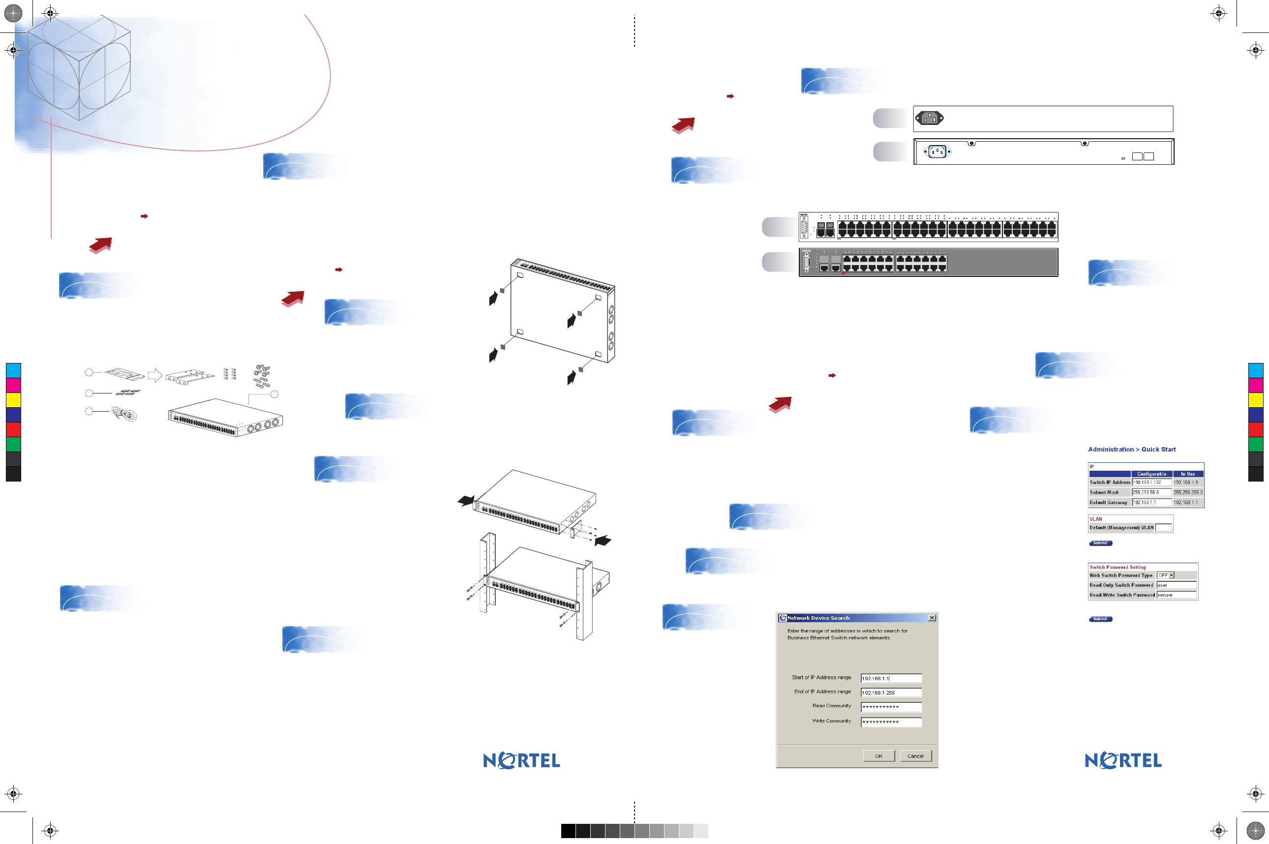
8. Connect the AC power cord to the back of the switch, and
then connect the cord to an AC power outlet.
Warning: You must use a line cord set approved for the
receptacle type in your country.
9. Check the
front-panel LEDs as
the device powers
on to be sure the
PWR LED is lit. If
not, check that the
power cable is
correctly plugged in.
The BES100 and BES200 series switches begin switching data as soon as you
attach network devices and connect the switch to the power supply.
With the BES200 series switch, traffic is switched across all units in the stack and
uses the 2 GBytes (gigabyte) of bandwidth across the stack connections as if it
were one switch.
10. To access the BES100 or BES200, first
install the Business Element Manager 1.0.
Refer to Element Manager documentation at
www.nortel.com for instructions.
11. Start the Element Manager.
12. From the Element Manager menu,
choose Network > Find Network
Elements > Business Ethernet Switch.
13. Enter the range
192.168.1.1 to
192.168.1.255, and
then click OK.
14. From the list of network
elements on the Element
Manager tree, select the
BES device.
15. Click the Web Page
button on the Element
Manager menu.
16. From the main menu,
choose Administration >
Quick Start.
The Quick Start screen
appears. It shows the IP
address and other items
that can be optionally
configured.
If you want to manually
assign IP addresses,
refer to the Business
Ethernet Switch 100/200
Series User Guide on
www.nortel.com.
Refer to Using the Nortel Business Ethernet
Switch 100/200 at www.nortel.com for detailed
installation instructions.
You are now ready to use the BES100 or
BES200 series switch in your network
installation.
25
26
1
2
4
6
8
10
12
3
5
7
9
11
13
14
16
18
20
22
24
15
17
19
21
23
25
26
28
30
31
33
35
27
29
31
33
35
37
38
40
42
44
46
48
39
41
43
45
47
Status
PWR
Speed
Link/Act
Reset
PoE
25
26
1
2
4
6
8
10
12
3
5
7
9
11
13
14
16
18
20
22
24
15
17
19
21
23
25
26
28
30
31
33
35
27
29
31
33
35
37
38
40
42
44
46
48
39
41
43
45
47
Status
PWR
Speed
Link/Act
Reset
PoE
25
26
1
2
4
6
8
10
12
3
5
7
9
11
13
14
16
18
20
22
24
15
17
19
21
23
25
26
28
30
31
33
35
27
29
31
33
35
37
38
40
42
44
46
48
39
41
43
45
47
Status
PWR
Speed
Link/Act
Reset
PoE
N0131605
7. If you are stacking the BES200 switches, the fixed, dedicated
1000BASE-T ports on the rear panel of the units can stack up to four BES
200 series switches. These fixed ports allow you to configure and manage
the switches as a single switch and control the flow of network traffic. The
cable connections need to cross over in the BES200 units so that the UP
port connects to the Down port of the next unit, and vice versa.
AC LINE
100-240 VAC
50-60 Hz
2.9 A MAX
Cascade Down Cascade Up
Unit Select
Base
25 26
1
2 4 6 8 10 12
3 5 7 9 11 13
14 16 18 20 22 24
15 17 19 21 23 25
26 28 30 31 33 35
27 29 31 33 35 37
38 40 42 44 46 48
39 41 43 45 47
Status
PWR
Speed
Link/Act
Reset
PoE PoE
AC LINE
100-240 VAC
50-60 Hz
xxx A MAX
BES 220-24T- PWR
Up
2422
2018
23
21
19
17
13
15
14
16
1
3
5
7
9
11
2
4
6 8 10
12
25 26
Down
Base
Status
PWR
Reset
Console
Speed
Link/Act Link/Act
PoE
PoE
C
M
Y
CM
MY
CY
CMY
K
BES100_200_QuickInstallGuide4.pdPage 1 8/24/2006 2:44:38 PM


