READ & SAVE THESE INSTRUCTIONS!
INSTALLATION INSTRUCTIONS
Timer Switches
1. The timer assembly is designed to mount in a 2-1/2" deep
single-gang box.
2.
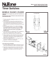
Run house power wiring (with ground) from fuse or
circuit breaker box and wiring from ventilation fan (refer
to fan motor plate for wiring instructions to motor) to
timer in outlet box and make connections as illustrated in
Figure 1.
3. Strip wires approximately 1/2" to make connections.
Connect wire to terminal screws in timer side. NOTE:
Use LINE-1/LOAD-1 for standard operation. LINE-
2/LOAD-2 will turn the current on at the end of
timing period.
4. Insert wired timer into wall box with “TOP” (indicated on
front cover) in proper position. Refer to Figure 2.
5. Fasten timer to wall box using (2) screws provided.
6. Fasten wall plate to timer using the (2) screws provided
with the plate. The screw must be self-tapped into the
timer body and will require a gentle inward pressure
while firmly turning the screw.
7. Position small plastic timer dial so that “OFF” is in the
up position. Install hex nut and tighten.
8. Push knob on shaft with the tail facing down.
Timer Operating Instructions:
1. Turn knob clockwise (to the right) to desired time period.
Timer will automatically turn “OFF” at the end of period.
2. Regardless of time period desired, knob must first be
rotated past “TURN PAST” as indicated on timer dial. It
may then be turned back to a shorter time period if
desired.
FIGURE 1
FIGURE 2
MODELS: VS-62WH, VS-63WH
CAUTION: Do not supply house power until installation is
complete.
All wiring must comply with local codes and switch must
be properly grounded.
TO NUTONE UNIT
120 VAC 60 HZ
HOUSE POWER
WHITE
(NEUTRAL)
BLACK (HOT)
GROUND
TIMER
EARTH
GROUND
(GREEN)
WHITE
(NEUTRAL)
BLACK (HOT)
TOP
“OFF”
POSITION