


2 – 1
2. THEORY OF OPERATION
2.1 Electrical Operation
The electrical operation of the printer circuit is described in this section.
2.1.1 Summary
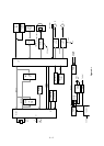
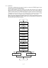
Fig. 2-1 shows the block diagram of the printer.
The control board is made up of the microprocessors, peripheral circuits, drive circuits, sensors
and interface connectors.
The power to the control board is supplied by the power board through the connector cord.
The power to other electrical parts is also distributed through the connectors within the control
board.
2.1.2 Microprocessor and the Peripheral Circuit
(1) Microprocessor (Q7: 67X640)
This processor is a CMOS single-chip computer with integrated peripheral device functions
and a 16 bit MPU core, all OKI original architecture.
The processor has a 20 bit address bus and a 16 bit data bus.
It is capable of accessing up to 1M word program memory and 1M bytes of data memory.
The following characteristics are also provided:
• Built-in type data memory of 512 bytes
• 8-bit 4-channel A/D converter × 1
• 16-bit automatic reload timer × 2
• 8-bit serial port × 2
• 8-bit parallel port × 3 (bitwise I/O specification available)
And others.
The function of this microprocessor is to provide a central mechanism for the entire printer
by executing the control program through the LSI and driver circuits.