


C – 11
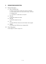
3.3 Local Test
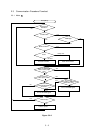
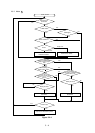
3.3.1 Circuit test mode
3.3.1.1Setting
(1) Diagnostic test (set by menu)
(2) Test connector
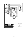
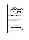
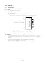
Connect the test connector shown in Figure C-3-6 to the interface connector
Figure C-3-6 Test Connector Connection Diagram
3.3.1.2Function
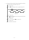
After the settings outlined in Section 3.3.1.1 are completed and power is turned on, the serial
interface checks the message buffer memory and interface driver/receiver circuit. It then prints
characters.
To start and stop this test, push the SEL switch on the front of the printer.
Details of this test are explained on the next page.
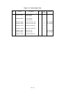
Equivalent to Cannon DB-25P
TD
RD
RTS
CTS
CD
SSD
DTR
DSR
2
3
4
5
8
11
20
6