


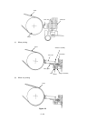
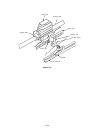
2 – 17
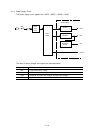
2.1.8 Alarm Circuit
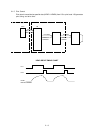
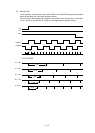
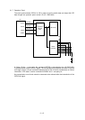
(1) Head drive time alarm circuit
This circuit monitors the drive time using the HDALM signal interlocked with the overdrive
signal of each drive circuit.
If the drive time of any drive circuit exceeds the specified time, the drive fault alarm circuit
sends an ALARM-N signal to turn on the SCR (SO).
This cause the secondary coil (40V) of the transformer to be short-circuited, causing an
overcurrent to flow through the primary coil and making the AC fuse (transformer assy)
open.
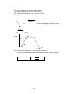
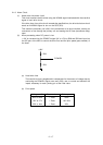
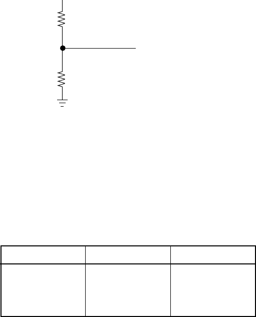
(2) Alarm processing when DC power is low.
+ 40V is converted into the POWLEV signal (0V to +5V) by R28 and R29 and input into
the A/D port of the MPU to control the drive time and the print speed (pass number) of
the head.
(a) Head drive time
The head drive time is lengthened to compensate for the amount of voltage drop by
monitoring the POWLEV signal once every 500 µ sec. to control and maintain the
impact necessary for each printing pin at the fixed value.
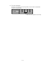
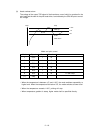
(b) Print speed
+40V
R28
R29
POWLEV
Voltage, +40V Pass number Print speed
38V or more 1 Pass 100%
25V to 37V 1 Pass 100~30%
25V or less 1 Pass 30%