2.6 8254 Timer/Counter
The 8254 Programmable timer/counter has 4 registers from Base+0 through Base+3. For
detailed programming information about 8254, please refer to Intel‘s “Microsystem
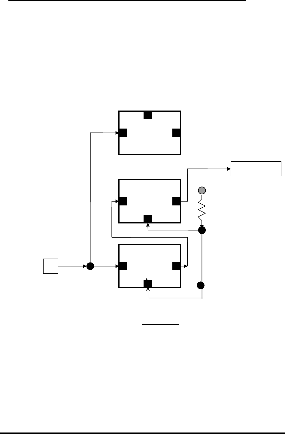
Components Handbook”. The block diagram is as below.
Cin: clock input
Cout: clock output
INTCLK: internal clock
Cin
Gate
Cout
Counter 0
Cin
Gate
Cout
Counter 1
Cin
Gate
Cout
Counter 2
2M
INTCL
K
VCC
10K
PACER CLK
Counter0, counter1 and counter2 are all 16 bit counters. Counter 1 and counter 2 cascade
as a 32-bit timer. The 32-bit timer is used as a pacer timer.
OME-A-8111 Hardware Manual (ver.1.1, Jul/2003) 20


