Technical Description
OMG-PCI-DIO48 Page 21
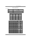
Interrupt control
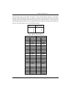
When enabled interrupts are generated on A10 and A20 (Pin 47 on each 50 pin header), for this
reason to use interrupts on a Port its A byte must be set as an input.
IRQENX interrupt enable 1 = enabled 0 = disabled ( 0 on power up )
IRQCX0
IRQCX1
Interrupt mode select see table
Interrupt mode select see table
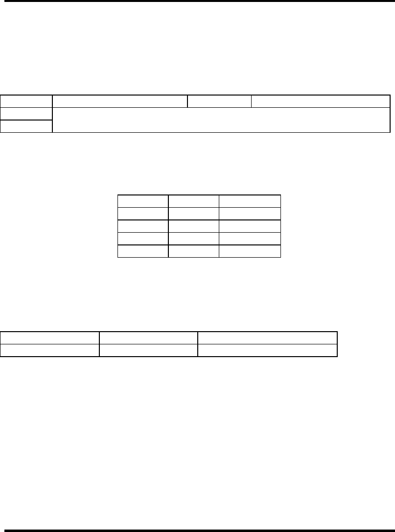
Figure 12-Interrupt Control
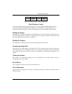
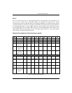
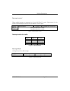
Interrupt mode select table
IRQCX1 IRQCX0 INT Type
0 0 Low level
0 1 High level
1 0 Falling edge
1 1 Rising edge
Figure 13-Interrupt Mode
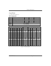
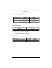
Interrupt Read
reading this port clears the interrupt
IRQST1 (D0) Interrupt status 1 = interrupt pending, 0 = none
IRQST2 (D4) Interrupt status 1 = interrupt pending, 0 = none
Figure 14-Interrupt Read


