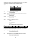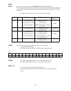
Write operations to this register allow the user to select interrupt sources, enable interrupts, and clear interrupts as
well as ADC FIFO flags. The following is a description of the Interrupt/ADC FIFO Register:
INT[1:0]
General Interrupt Source selection bits.
AD FIFO Not Empty11
AD FIFO Half Full01
End of Channel Scan10
Not Defined 00
SourceINT0 INT1
INTE
Enables interrupt source selected via the INT[1:0] bits.
1 = Selected interrupt Enabled
0 = Selected interrupt Disabled
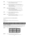
EOAIE
Enables End-of-Acquisition interrupt. Used during FIFO'd ADC operations to indicate that the
desired sample size has been gathered.
1= Enable EOA interrupt
0 = Disable EOA interrupt
EOACL
A write-clear to reset EOA interrupt status.
1 = Clear EOA interrupt.
0 = No effect.
INTCL
A write-clear to reset INT[1:0] selected interrupt status.
1 = Clear INT[1:0] interrupt
0 = No effect.
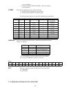
ADFLCL
A write-clear to reset latched ADC FIFO Full status.
1 = Clear ADC FIFO Full latch.
0 = No Effect.
NOTE: It is not necessary to reset any write-clear bits after they are set.
READ
------EOAIINT-EOBIADHFIADNEIADNELADFUL--
0123456789101112131415
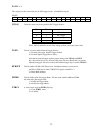
Read operations to this register allow the user to check status of the selected interrupts and ADC FIFO flags. The
following is a description of Interrupt / ADC FIFO Register Read bits:
EOAI
Status bit of ADC FIFO End-of-Acquisition interrupt
1 = Indicates an EOA interrupt has been latched.
0 = Indicates an EOA interrupt has not occurred.
INT
Status bit of General interrupt selected via INT[1:0] bits. This bit indicates that any one of
these interrupts has occurred.
1 = Indicates a General interrupt has been latched.
0 = Indicates a General interrupt has not occurred.
20


