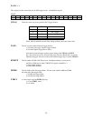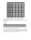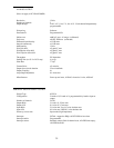
ININININ1111
OUTINININ0111
INOUTININ1011
OUTOUTININ0011
ININOUTIN1101
OUTINOUTIN0101
INOUTOUTIN1001
OUTOUTOUTIN0001
INININOUT1110
OUTININOUT0110
INOUTINOUT1010
OUTOUTINOUT 0010
ININOUTOUT1100
OUTINOUTOUT0100
INOUTOUTOUT1000
OUTOUTOUTOUT0000
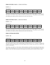
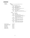
PORT C
LOWER
PORT BPORT C
UPPER
PORT AD0D1D3D4
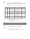
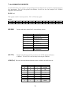
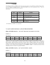
7.5.3 INDEX and USER COUNTER DATA AND CONTROL REGISTERS
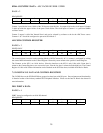
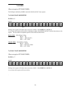
8254B COUNTER 0 DATA
—ADC PRE-TRIGGER INDEX COUNTER (or USER
COUNTER #4)
BADR3 + 8
READ/WRITE
D0D1D2D3D4D5D6D7
01324567
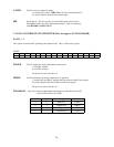
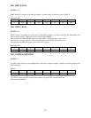
Counter 0 of the 8254B device is a shared resource on the PCI-DAS1200. When not in ADC pre-trigger mode, the
clock, gate and output lines of Counter 0 are available to the user at the 100-pin connector as User Counter 4. The
Counter 0 clock source is SW selectable via the
C0SRC
bit in BADR1+4.
When in ADC Pre-trigger mode, this counter is used as the ADC Pre-Trigger index counter. This counter serves to
mark the boundary between pre- and post-trigger samples when the ADC is operating in Pre-Trigger Mode. The
External ADC Trigger flip flop gates Counter 0 on; the ADC FIFO Half-Full signal gates it off. Knowing the desired
number of post-trigger samples, software can then calculate how may 1/2 FIFO data packets need to be collected and
what corresponding residual sample count needs to be written to BADR3 + 0.
31


