


M-4623/0208
FSW-410 Series
Thermal Flow Switches
1.0 Install the FSW-410 by inserting the 1/2” MNPT threaded sensor tip into
a tapped pipe or T fitting. Use Pipe Tape or Plumbers Putty on NPT
threads to aid in sealing. Tighten firmly, but do not over tighten as this
could damage the NPT threads and prevent proper sealing.
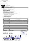
2.0 With provided connection cable disconnected, complete unit wiring by
connecting the Brown wire to +24VDC supply and the Blue wire to
common. The Black wire is now connected to the + side of your load.
The - side or common side of the load is now connected to the ground.
.
NOTE: Be sure that the common (ground) of the FSW-410 and the
LOAD are the same. The white wire (if present) is not used.
3.0 Upon initial power-up the unit will provide a temporary output as the unit is
adjusting to the zero flow rate of the media. After approximately 10-15
seconds the output will turn off. Once the unit output has turned off, the
unit is ready for operation. Once the threshold of the unit set point
(approx. .3-.4 meters/second) is reached the output will turn on.
4.0 As the FSW-410 unit also monitors the media temperature, the unit will
provide a loss of signal if the temperature of the media goes above the
threshold of the unit temperature set point (typically 50 or 70 Deg. C.),
even with proper media flow.
NOTE:
Use caution while installing the FSW-410 so as not to damage the tip of the sensor. The
electronics are embedded just behind the tip of the FSW-410 and denting or bottoming
out of the tip could cause damage.
Maintenance is not required, as the FSW-410 has no moving parts. However, should the
sensor become coated after a period of time in operation due to water or media conditions,
simply wipe the probe tip with a soft cloth and alcohol.
FSW-410 SERIES INSTALLATION & INSTRUCTION SHEET