Equipment Installation
(.. /continued)
Tip: Always test all equipment at the workbench before
installing them at their final positions.
Example Installations
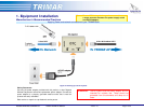
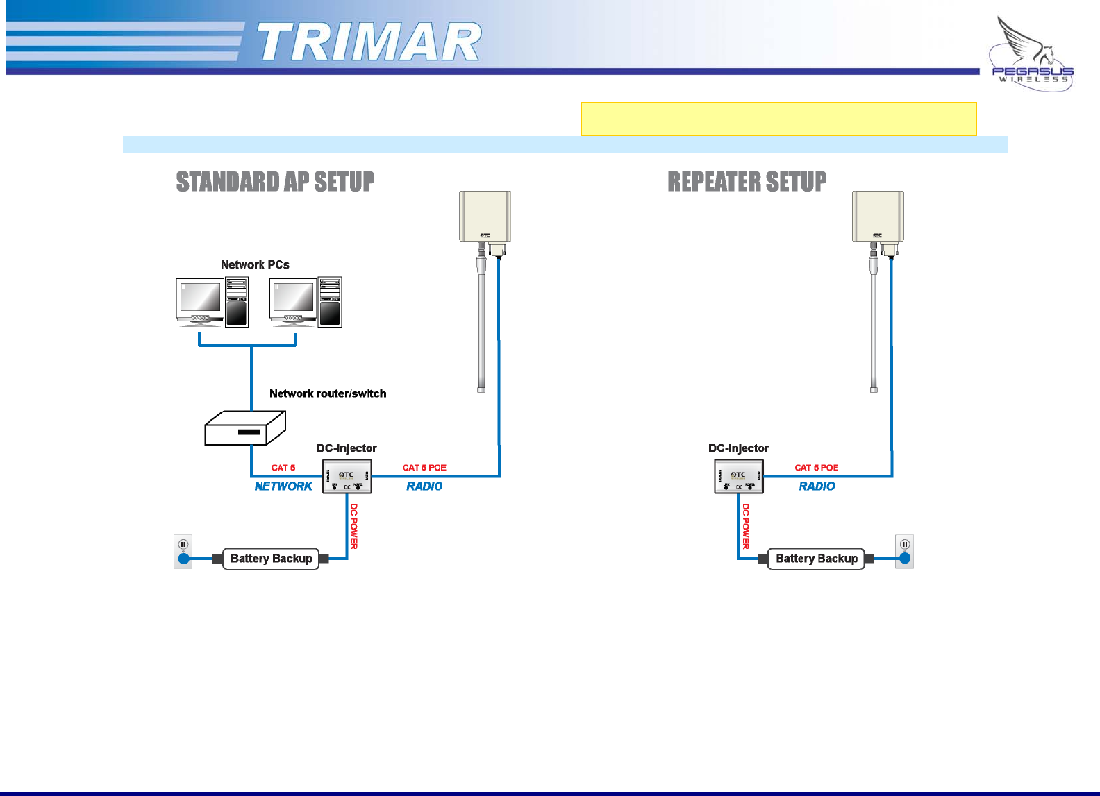
Figure 4: Typical TRIMAR deployment schematic
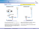
Figure 5: TRIMAR repeater mode schematic
Figure 4 above illustrates a common wiring scheme for a TRIMAR radio unit
that is physically connected to the network.
A set up like this can be used to connect with another TRIMAR radio in a
separate building that is wired similarly to form the basis of a wireless
point-to-point bridge. Alternatively, it can be connected wirelessly with
TRIMAR repeaters (as shown in Figure 5) to form a larger wireless mesh.
In both of these types of operations, the TRIMAR APs need to be
configured to operate in WDS mode.
Figure 5 illustrates a TRIMAR radio used as a repeater. In this type of
deployment, no physical connection to the network is necessary, all
communications is done via the 802.11 wireless connections.
To work in this mode, the TRIMAR radio must be configured using WDS
and connected wirelessly to at least one radio that is physically connected
to the network being serviced.
PEGASUS WIRELESS CORPORATION TRIMAR TECHNICAL MANUAL Version 1.0 Page 8 of 32


