9-27
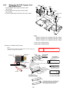
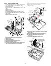
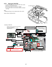
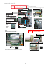
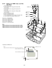
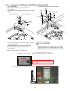
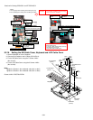
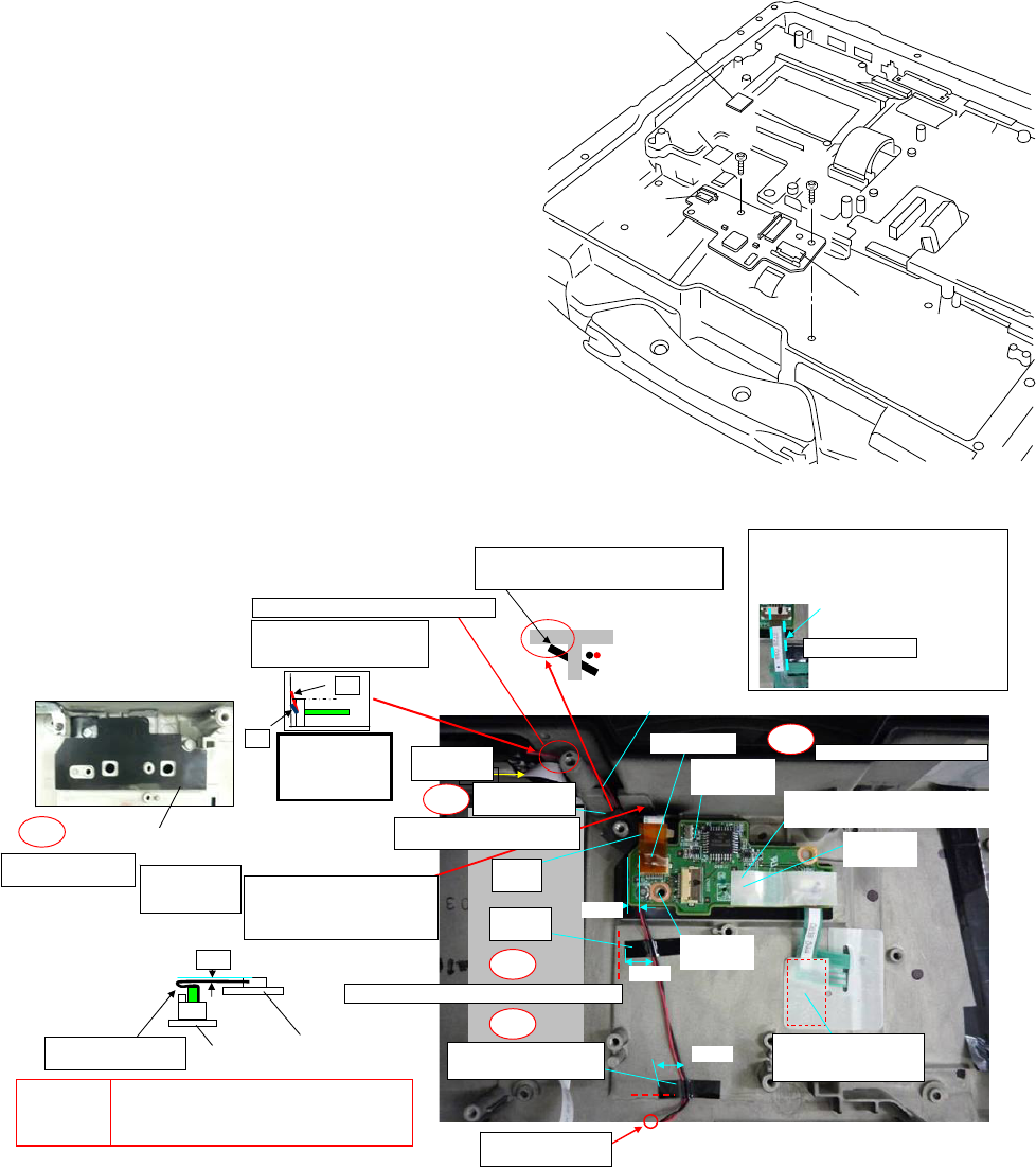
9.2.11. Setting the PAD PCB
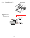
1. Fix the PAD PCB using the 2 Screws <N29> (No1 to No2).
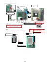
2. Attach the TP PCB Screw Sheet.
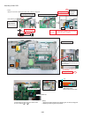
3. Connect the Cable to the Connector. (CN802)
4. Connect the Cable to the Connector (CN801) and attach
the Tape.
Note:
Tighten the Screws in the numbered order (No1 to No2).
Screws <N29>: DRQT26+E3FNL
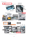
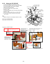
Assembly of PAD PCB
Pad PCB
Connector
(CN802)
Connector
(CN801)
Tape
TP PCB Screw Sheet
<N29>
<N29>
No.1
No.2
<N29>
<N29>
No.1
No.2
7䌾11
7䌾11
0㫧2
NG
OK
2㫧1
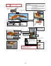
CAUTION
S1:Insulation S2:Bitten S3:Sharp Edge
S4:Part No. Check S5:Other
1. Apply the load when attaching the attaching parts.
20 to 30N (2 to 3Kgf)/cm2
2. Reusing the attaching parts is prohibited.
Tightening torque
TAPE Attach
After inserting FFC, confirm
it is not diagonal insertion, and then
attach.(To prevent coming off)
Confirm it is not diagonal.
Example of NG
Insert into the boss at an angle to
put here close to the Cabinet side.
Avoid running over the top of boss
Ensure the wire does not
protrude from the top of
boss.
Confirm the
processed wire
View from A
direction
Insurate the Board
and Cabinet.
Avoid running
over the boss
and the rib.
When pressing not to touch
the Cabinet wall, be careful
not to bend
the FFC stiffening plate.
Process the surplus
of FFC to the back
TP INS SHEET
Attach
Process the wire
targeting the boss
Fix with Screws in order of the rear number of No.
Ex.) Fix in order of Screw-1 to Screw-2.
Remove the Release
Paper and process
the FPC
TAPE-2 Attach
Fit to the Cabinet line
Avoid catching the Cable in the Cabinet
TAPE
Attach
TAPE-1
Attach
CABLE HOLD
SHEET Set
View from
A direction
Process the SP Cable between the bosses.
Insert FFC
PWB PAD
Set
Insulate the Screw head
TP PCB Screw SHEET Attach
Match to the end of the Board
Tighten
Screw-2
Tighten
Screw-1
Torque of tightening Screw :
0.45
±
0.05
N·m(Ṑ
4.5
±
0.5
kgf·cm)
S1
S1
S2
S2
S2
Line involved prevention
to the boss of the SP cable
PWB䇭PAD
LED PWB


