


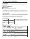
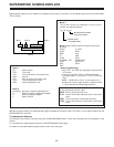
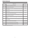
Block 3
The counter values are displayed in units of hours,
minutes, seconds and frames.
Block 4 (when T&STA is set for the set-up menu item
No. 000)
EJECT E_PLAY
STOP SHTL
REW JOG
FF VAR
STOP PPLY
STANDBY_OFF POWER OFF
PLAY AUTO OFF
REC DEW
EDIT
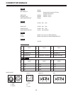
• Search speed display
• REV, SHTL and FWD are displayed during external
VTR control.
• In the jog mode, REV, STILL or FWD is displayed.
• The tape speed is displayed in SHTL, VAR and
PPLY.
SHTL – 32.0 (where “32.0” is the speed and “–”
denotes the reverse tape direction (compared with
“+” which denotes the forward tape direction)
Block 4 (when T&YMD, T&MDY, T&DMY or T&RT is set
for the set-up menu item No. 000)
DATE: Date on which tape was shot
D*TE: Date on which tape was shot (when it cannot be
read)
TIME: Time (hr/min/sec) at which tape was shot
T*ME: Time at which tape was shot (when it cannot be
read)
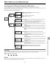
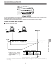
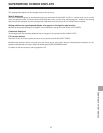
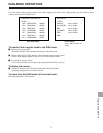
Superimposed displays can be added to the laptop’s liquid-crystal TV monitor or to the signals output from the VIDEO MONI-
TOR connector.
With the on-screen display, the superimposed signals are added to the liquid-crystal TV monitor or to the signals output from the
VIDEO MONITOR connector.
To superimpose displays:
First check the connections, and then press the COUNTER/REMAIN switch. Check that characters are now displayed on the
monitor.
If no characters are superimposed, press the COUNTER/REMAIN switch again.
For details on the superimposed display function, refer to the next page.
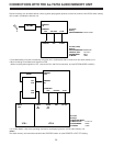
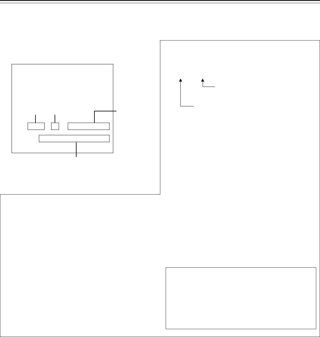
SUPERIMPOSE SCREEN DISPLAYS
66
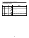
TCR
SHTL + 32.0
12 : 34 : 43 : 21
Block 1 Block 2 Block 3
Block 4
12 : 34 : 43 : 21
: Non-drop frame mode
. Drop frame mode
: Normal mode
.
Time track mode
Block 1
CTL : Control signal
TCR : Time code
T*R : Time code (when it cannot be read)
UBR : User bit
U*R : User bit (when it cannot be read)
TCG : Time code generator value
UBG : User bit generator value
Block 2
No display : Normally, nothing is displayed here.
P : When the supply voltage has dropped
S : When the fan has stopped
L : When LOW RF