11
RESET
No.
MODE
qwe
VIDEO OUT 3
VIDEO OUT 4
VIDEO OUT 2
IN X-2
VIDEO OUT 1
ALARM IN
IN X-1
16
32
15
31 30
14 13
29 28
12 11
27 26
10 9
25
CAMERA IN
24
87
23 22
65
21 20
43
19 18
21
17
EXTENSION 3 IN
EXTENSION 2 IN
4
MODE
RS485 (CAMERA) RS485 (CAMERA)
3
MODE MODE MODE
2
1
IN C-3
IN C-3 board
IN X-2 board
IN X-1 board
uu
i
!0
!1
4
3
MODE
RS485 (CAMERA) RS485 (CAMERA)
MODE MODE MODE
2
1
IN B-3
MODE
RS485 (CAMERA) RS485 (CAMERA)
MODE MODE MODE
4
3
2
1
EXTENSION 1
TERM.
OFF
ON
OUT
IN
IN A-3
EXTENSION 3 OUT
EXTENSION 2 OUT
IN A-3 board
IN B-3 board
tuur
i
y
oy
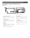
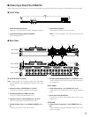
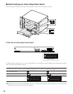
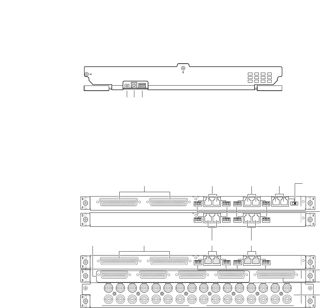
■ Video Input Board WJ-PB65C32
Video input board is composed of a main board (installed into the front side) and rear boards (x 3)(installed into the rear side).
● Front View
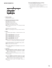
q Board Number Switch (No.)
Refer to p. 51 Board Number Switch Settings for details.
w Input Mode Selection Switches (MODE)
Set all switches to OFF.
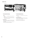
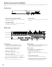
● Rear View
IN A-3/IN B-3/IN C-3 board
Note: These boards are originally installed into WJ-SX650
and WJ-SX650U. (Not supplied to optional video input
boards)
r Extension Ports 1 (EXTENSION 1: IN, OUT)
These ports connect to an optional card cage.
t Termination Selector (TERM: ON, OFF)
Turns on or off the line termination of r.
y Extension Ports 2, 3 (EXTENSION 2, 3: IN, OUT)
Each port connects to an optional card cage.
u RS-485 Camera Ports 1 to 4 (RS485 (CAMERA) 1 to
4)
These ports connect to RS-485 cameras.
i RS-485 Camera Mode Switches 1 to 4 (MODE 1 to 4)
These switches are moved to change the communica-
tion modes of
u.
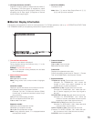
IN X-2 board
o Video Output Ports 1 to 4 (VIDEO OUT 1 to 4)
These ports loop through video input signals supplied
to
!1.
!0 Alarm Input Port (ALARM IN)
Connects to an alarm input device (alarm sensor, door
switch, etc.).
IN-3 board
!1 Camera Input Connectors 1 to 32 (CAMERA IN 1 to
32)
These connectors accept video input signals from cam-
eras or recorders.
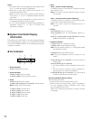
e Reset Switch (RESET)
This button is pressed to reset this board.
Note: In normal operation, you need not press the but-
ton.


