


INSTALLATION INSTRUCTIONS PN79G
© Panduit Corp. 2007
For Technical Support: www.panduit.com/resources/install_maintain.asp
Page 1 of 2
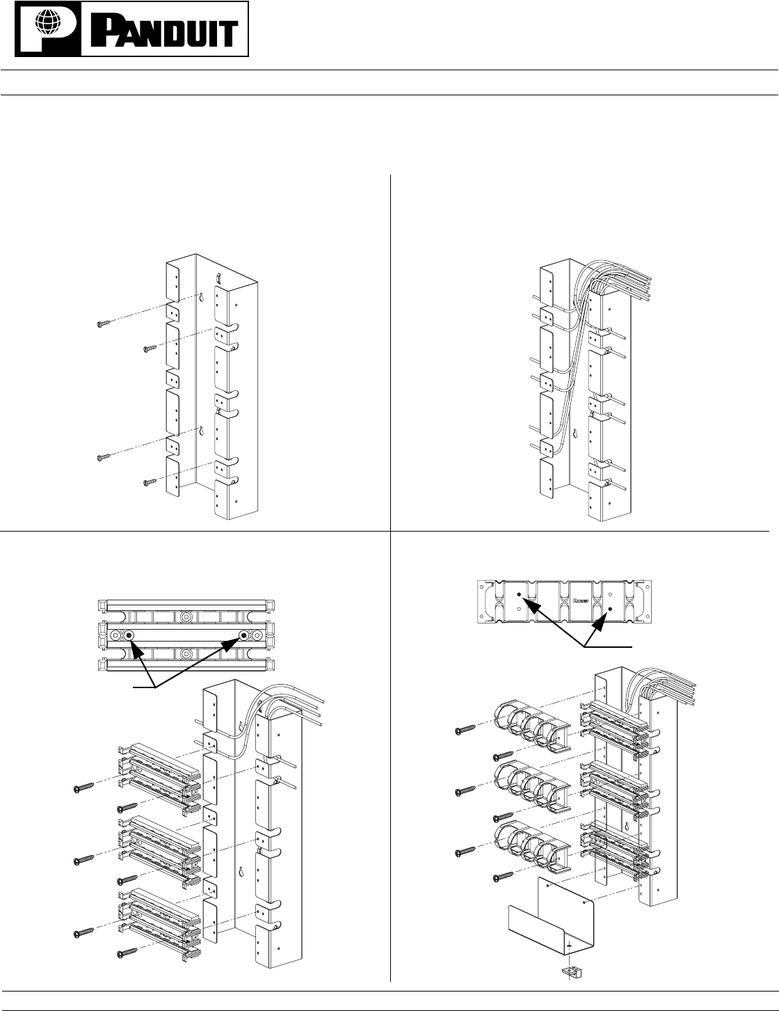
4. Install jumper troughs between bases with two #12 sheet metal
screws (supplied).
PAN-PUNCH 110 Tower System
NOTE: 300 PAIR TOWER SHOWN. INSTRUCTIONS ALSO APPLY TO THE 900 PAIR TOWER.
CABLE REQUIREMENT: Terminates most 22-26 AWG solid or stranded
IWC wire with a .050" (1.27mm) max. o.d., either PVC or Plenum rated.
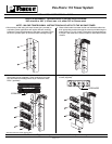
1. Mount tower to wall using #12 wood screws (not provided) or
equivalent. Some applications will require different mounting
hardware. Ensure that the bottom of the tower is at least 8" from
the floor to provide space for horizontal cable manager trough.
2. Route cable bundle into tower and fan out individual cables into
their appropriate positions through the cutouts provided along the
tower leaving 12" to 18" of slack. Each cutout accommodates up
to 25 pair. Use cable ties to secure bundle to raised tabs on back
of tower.
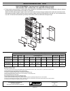
3. Position base over slots in tower and secure with two #12
sheet metal screws (supplied). Place conductors into index
strip and install connecting blocks as per instruction sheet
PN51* (provided).
SCREW HERE
SCREW HERE
* Denotes instruction sheet revision letter.