Pelco Manual C653M-D (9/03) 5
OUTPUT CONNECTIONS
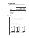
Perform the following steps to attach 24 VAC devices to the MCS Series Power Supply:
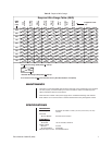
1. Refer to Tables C and D in this manual or the wiring table on the unit’s lid to determine
the output wiring needed for your devices.
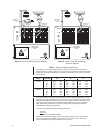
2. Refer to Figure 2 (or Figure 3 for “S” and “SB” models) for the proper connector strip
connections, and do one of the following:
• Regular MCS Models: For each device, attach one output wire to the COM
(common) terminal. Attach the second wire to the appropriate 24V or 28V terminal.
• “S” and “SB” (Switched) Models: For each device, attach one output wire
to the COM (common) terminal and the second wire to the 24/28V terminal.
3. When you finish the wiring connections, double-check the installation for safety
purposes.
4. Power up the unit with the on/off switch. On MCS “S” and “SB” (switched) models,
move the switch to the appropriate output voltage position (up = 24 VAC, down = 28
VAC) to provide power.
5. Use a voltmeter to verify that used outputs are at appropriate voltage levels.
6. Close the lid and secure it using the 8-32 Phillips screw.
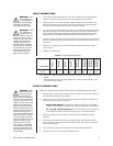
CAUTION:
Under
light load conditions
and high power line
input voltage from the utility
company, output voltage from
the power supply (28 VAC taps
only) may reach 32 VAC. This
voltage can cause over-voltage
damage on 24 VAC devices.
Keep in mind, certain devices
produce variable loads (due to
heaters, blowers, and pan and
tilt motion) and during mini-
mum requirements may create
a light load condition, causing
excessive voltage. Therefore,
Pelco recommends using a 28
VAC tap only when the sup-
plied wire size for the given
load causes an unacceptable
output voltage on the 24 VAC
tap. Refer to Table D to deter-
mine acceptable situations for
the 28 VAC tap.
INPUT CONNECTIONS
1. Verify that the on/off switch inside the box is OFF. On MCS “S” and “SB” (switched)
models, verify that the switch for each output is at the center (OFF) position.
2. Refer to Figure 2 or 3. Remove the high-voltage compartment panel inside the box.
Set the input voltage selector switch inside the compartment to the appropriate line
voltage. The switch is set at the factory for 120 VAC line voltage.
3. If you are using 120 VAC line voltage, go to step 4. If you have a fuse model and are using
240 VAC line voltage, remove the 120 VAC fuse from the fuse holder directly above the
power switch and install the appropriate fuse (refer to Table B). Find the fuse in the bag
located inside the high-voltage compartment. (Extra fuses are supplied for spares.)
4. Attach the 120/240 input wires to the flying leads in the compartment with the supplied
wire nuts. Connect the black wire to the AC line lead. Connect the white wire to the AC
neutral lead.
5. Attach the input ground wire to the stud inside the compartment with the supplied
washer and nut.
6. Replace the access panel.
WARNING:
Pelco
shall not be liable
for any damages re-
sulting from incorrect wiring
or improper loading of an
MCS Series Power Supply.
WARNING:
Units
are equipped for
120 VAC line volt-
age at the factory. If you are
using 240 VAC, you must
change the main fuse (fuse
models) and change the
voltage selector switch. If
240 VAC power is applied
with the selector switch set
to 120 VAC, the main fuse
will blow (fuse models) or
the thermal breaker will
open (breaker models).
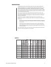
Table B. Fuse Determination Table
Line Voltage
120 VAC 1 A 1 A 1.6 A N/A 3 A N/A 5 A N/A
240 VAC 0.5 A 0.5 A 1 A N/A 1.6 A N/A 3 A N/A
N/A - Model is not equipped with a primary input fuse; transformer is protected with thermal
breaker.
* - MCS4-2B uses a fuse for the high-voltage line input and provides breakers for the
low-voltage output channels.
MCS4-2
MCS4-2B*
MCS8-5
MCS8-5B
MCS16-10/
MCS16-10S
MCS16-10B/
MCS16-10SB
MCS16-20/
MCS16-20S
MCS16-20B/
MCS16-20SB


