This upgrade kit is designed for upgrading CM6700 matrix switchers to the latest software
revision. By installing this PROM, the CM6700 will operate with 3.02 software. Contact Pelco
24-hour technical support at (800) 289-9100 with any questions or concerns about the procedures
described below.
Contents of this package:
1 CM6700 CPU, p/n ICO80C32-24
1 CM6700 software PROM, version 3.02, p/n IC53-0021-0300
1 Chip puller
To change the CPU and PROM chips on the CM6700 motherboard:
1. Unplug the system.
2. Remove the top cover of the switcher/controller unit. If you have an MXB2, proceed
to step 4.
3. MXB4 models require the removal of the two-monitor expansion card to reach the PROM
chips. The two-monitor expansion card is the 5-inch x 11-inch printed circuit board mounted
to the motherboard.
Do the following process carefully to avoid damaging sensitive electronic components.
a. Remove the five screws and washers holding the expansion card in place.
Do not try to pull the expansion card out all at once. There are 128
connecting pins on the card and removal takes patience.
b. Lift along the exposed edge of the card at each connector, a little at a time, until the
card is removed. Put it safely aside.
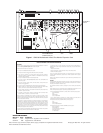
4. Remove the old CPU and PROM chips (see Figure 1) from their sockets using the chip
puller included in this package. Work the parts out slowly to avoid damaging the sockets.
5. Remove the new CPU and PROM chips from the electrostatic bag and verify that their
pins are straight.
6. Orient each chip using the alignment notch as a guide (see Figure 1). Verify pin-to-socket
alignment and carefully press each chip into its socket until completely seated. If you
have an MXB2, proceed to step 10.
7. Very carefully position the two-monitor expansion card for installation. Be absolutely
sure the pins on the expansion card are completely aligned with the connectors on the
motherboard.
8. Once the pins are aligned, press the expansion card into place until the connector pins
are completely seated.
9. Replace the washers and screws that hold the expansion card and tighten.
10. The installation is complete. Replace the cover and apply power.
C531M-A (8/99)
CM6700 CPU and
Software Upgrade Instructions
3500 Pelco Way,
Clovis, CA 93612-5699
USA
In North America & Canada:
Tel (800) 289-9100
FAX (800) 289-9150
International Customers:
Tel (1-559) 292-1981
FAX (1-559) 348-1120
www.pelco.com
®
IMPORTANT:
Performing the
CM6700 upgrade erases all
programmed information. You
should document all programming
information before proceeding.
CAUTION:
Only
qualified personnel
observing electrostatic
discharge (ESD) precautions
should perform the procedures
in this document. Always wear a
grounding strap connected to an
approved grounding source
when working on or around
exposed electronic components.
Handle circuit boards by their
edges.