


Philips Semiconductors Product specification
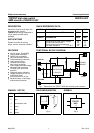
TOPFET high side switch BUK215-50Y
SMD version of BUK210-50Y
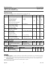
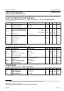
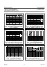
OVERLOAD PROTECTION CHARACTERISTICS
5.5 V ≤ V
BG
≤ 35 V, limits are at -40˚C ≤ T
mb
≤ 150˚C and typicals at T
mb
= 25 ˚C unless otherwise stated.
Refer to TRUTH TABLE.
SYMBOL PARAMETER CONDITIONS MIN. TYP. MAX. UNIT
Overload protection V
BL
= V
BG
I
L(lim)
Load current limiting V
BG
≥ 9 V 34 45 64 A
Short circuit load protection
V
BL(TO)
Battery load threshold voltage
1
V
BG
= 16 V 8 10 12 V
V
BG
= 35 V 15 20 25 V
t
d sc
Response time
2
V
BL
> V
BL(TO)
- 180 250 µs
Overtemperature protection
T
j(TO)
Threshold junction 150 170 190 ˚C
temperature
3
∆T
j(TO)
Hysteresis - 10 - ˚C
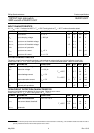
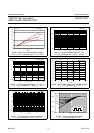
SWITCHING CHARACTERISTICS
T
mb
= 25 ˚C, V
BG
= 13 V, for resistive load R
L
= 13 Ω.
SYMBOL PARAMETER CONDITIONS MIN. TYP. MAX. UNIT
During turn-on from input going high
t
d on
Delay time to 10% V
L
-4060µs
dV/dt
on
Rate of rise of load voltage 30% to 70% V
L
- 0.35 1 V/µs
t
on
Total switching time to 90% V
L
- 140 200 µs
During turn-off from input going low
t
d off
Delay time to 90% V
L
-5580µs
dV/dt
off
Rate of fall of load voltage 70% to 30% V
L
- 0.6 1 V/µs
t
off
Total switching time to 10% V
L
- 85 120 µs
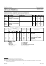
CAPACITANCES
T
mb
= 25 ˚C; f = 1 MHz; V
IG
= 0 V. designed in parameters.
SYMBOL PARAMETER CONDITIONS MIN. TYP. MAX. UNIT
C
ig
Input capacitance V
BG
= 13 V - 15 20 pF
C
bl
Output capacitance V
BL
= 13 V - 250 350 pF
C
sg
Status capacitance V
SG
= 5 V - 11 15 pF
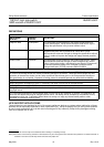
1 The battery to load threshold voltage for short circuit protection is proportional to the battery supply voltage. After short circuit protection has
operated, the input voltage must be toggled low for the switch to resume normal operation.
2 Measured from when the input goes high.
3 After cooling below the reset temperature the switch will resume normal operation.
May 2001 6 Rev 1.010