


11 ENGLISH
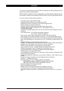
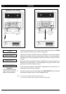
figure 2
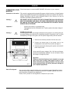
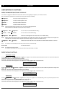
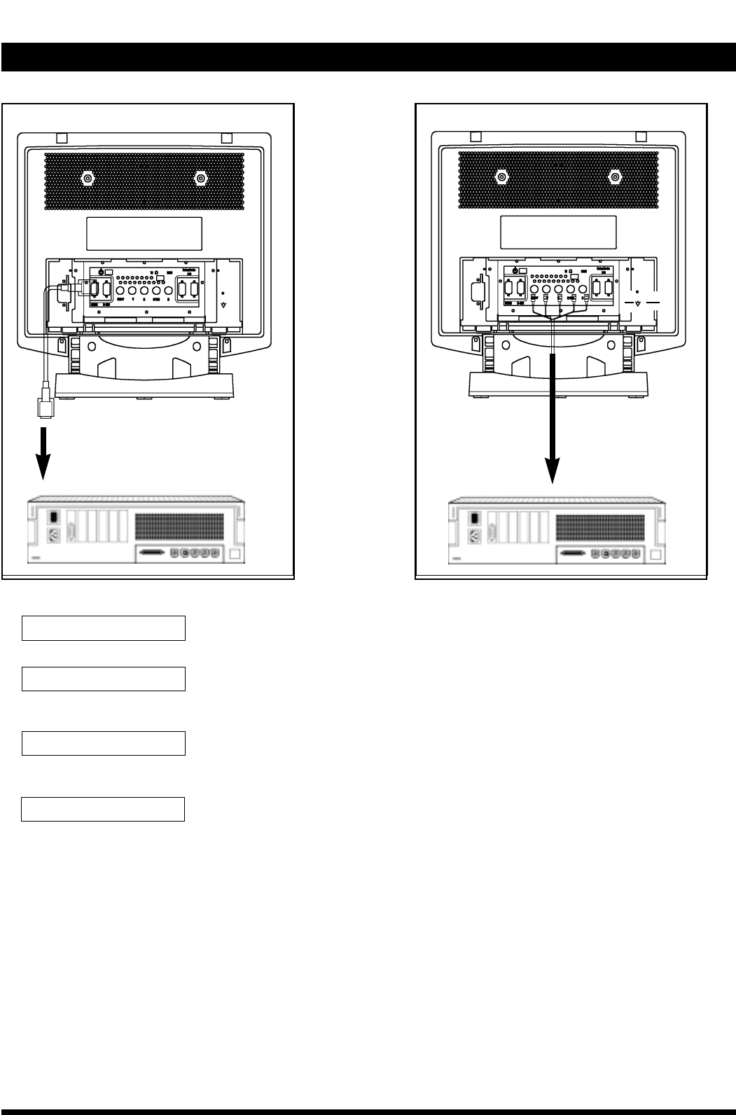
Connection to the computer
1. Connect the male plug of the mini D-Sub 15 pins cable (optional) to the D-SUB
input connector at the rear of the monitor (see figure 2).
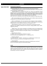
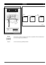
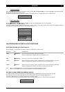
2. (Alternative) Connect the BNC connectors (VIDEO/H/V) of the video cable to
thesocket on the back of the monitor as shown in figure 3. In this configuration,
the three guns will be automatically ‘locked’ (the monitor is driven as ‘mono-
chrome’).
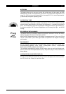
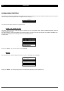
3. (Alternative) Connect the BNC connectors (R/G/B/H/V) of the video cable to the
socket as in § 2. (see figure 4). In this configuration, the guns are driven inde-
pentently (the monitor is seen as ‘colour’).
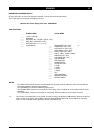
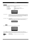
4. If you use some monitors in Daisy Chain configuration, the units shall be con-
nected each other as shown in figure 5.
5. Connect the other end of the video cable to the VIDEO OUTPUT of your PC (with
high resolution graphic card or usual VGA graphic card).
Note: The monitor automatically recognizes the connected input.
The 15 pins D-Sub interface cable complies with VESA DDC1/2B standard.
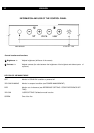
D-SUB
VIDEO H/H+V V
Important !
to prevent bad connection
and to ensure a proper fit,
tighten the thumbscrews.
RGB H/H+V V
DAISY CHAIN
figure 3