


21 ENGLISH
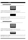
´SET
ADDRESS
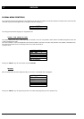
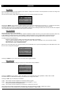
This function allows to assign an unique address to each monitor in a Daisy Chain connection. This local operation is executed once during instal-
lation. The address can be in the range 1-15.
Note: Care must be taken to assign different addresses to each of the monitors connected in one Chain.
Each time the “SELECT” key is pressed, the address displayed on the window is incremented by one unit (set to 1 if ‘--’) and saved in the memory
of the monitor. When the address “15” is reached a further key press shall set it to ‘--’ (this simbol indicate no address assigned).
Note: When replacing one unit in an existing dasy chain installation, please take care of setting the address of the new unit the same of the replaced
one, to avoid dasy-chain conflict between two units having the same address.
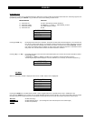
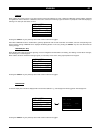
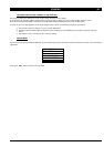
´DAISY CHAIN MODE
Each monitor has 2 modes of control operation:
DAISY-CHAIN MODE option OFF for local operation: RS232, KEYBOARD and ABC controls are just executed LOCALLY (inside the monitor unit).
In this condition no command sequence is sent (trasmitted) to Daisy-Chain interface and no command will be received from the Chain.
DAISY-CHAIN MODE option ON the controls are trasmetted to the other monitors and all applicable received controls are executed.
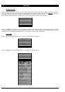
The Daisy-Chain Control commands are:
Brightness, Contrast, Reference Setting, User Setting, Store User Setting, via Keyboard;
1-GUN / 3-GUNS, DEGAUSS, KEYLOCK, (ALL / STORE / CNTRL), ABC (FULL / REDUCED / OFF), REF. SETTING (1/2/3/4/5)
ABC MASTER OFF, via On Screen Display selection.
ABC measurement control and RS232 Commands
When a unit is set to Daisy Chain OFF, it shall automatically reset to ABC Master OFF, to prevent the possibility to set to ABC Master ON in more
than one unit in a Daisy Chain configuration.
Pressing the “SELECT” key, the active mode of this function item is toggled (ON/OFF).
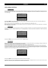
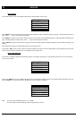
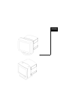
´INPUT SELECTION
This function allows to choose the setting of the proper input mode between three possibilities:
Pressing the “SELECT” key, the ‘INPUT = <SEL>’ item displays the next selection among three possibilities: 1-BNC, 3-BNC, D-SUB.
The current choice is not activated immediately, to avoid the loss of the image on the screen.
Pressing the “EXIT” key, the selected input is activated.
1-BNC: when selected, the video amplifier input is switched to BNC V2 (green).
3-BNC: when selected, the video amplifier input is switched to three BNC: V1, V2, V3.
Each gun is connected to the single BNC input.
D-SUB: when selected, the video amplifier input is switched to 15 PINS D-sub connector.
Note: If the previous selection of the brightness mode item was 1-GUN, after activation of D-SUB or 3-BNC mode, it will be
automatically forced to 3-GUN LOCKED (see also GLOBAL MENU CONTROLS - 3-GUN/1-GUN).
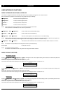
LOCAL MENU
SEL EXIT - +
POWER SAV. ON
AUTO DEG. OFF
DAISY ADDR. 1
LOCAL MENU
SEL EXIT - +
AUTO DEG. OFF
DAISY ADDR. 4
DAISY CH. ON
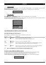
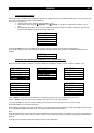
LOCAL MENU
SEL EXIT - +
DAISY ADDR. 6
DAISY CH. ON
INPUT = 3-BNC