


Philips Semiconductors
User’s Manual - Preliminary -
P89LPC906/907/908
TIMERS 0 AND 1
2003 Dec 8 45
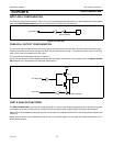
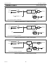
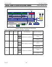
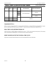
Figure 5-7: Timer/Counter 0 Mode 3 (two 8-bit counters)
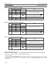
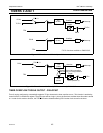
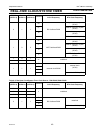
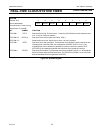
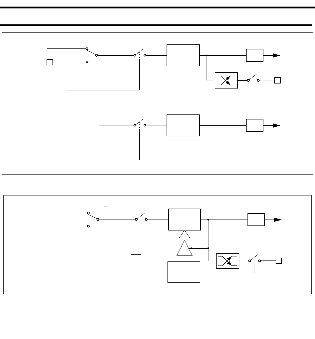
Figure 5-8: Timer/Counter 0 in Mode 6 (PWM auto-reload), P89LPC907.
TIMER OVERFLOW TOGGLE OUTPUT - P89LPC907
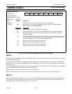
Timer 0 can be configured to automatically toggle the T0 pin whenever the timer overflow occurs. This function is enabled by
control bit ENT0 in the AUXR1 register. The port output will be a logic 1 prior to the first timer overflow when this mode is turned
on. In order for this mode to function, the T0C/T
bit must be cleared selecting PCLK as the clock source for the timer.
TL0
(8-bits)
TR0
T0 Pin*
C/T
= 0
C/T
= 1
Interrupt
T0 Pin*
Control
Toggle
ENT0
TF0
PCLK
Overflow
TH0
(8-bits)
Interrupt
Control
TF1
Overflow
TR1
PCLK
* T0 Pin functions available on P89LPC907
TL0
(8-bits)
TR0
T0C/T = 0
TH0
(8-bits)
Interrupt
T0 Pin
Control
Toggle
ENT0 (AUXR1.4)
TF0
PCLK
Reload TH0 on falling transition
Overflow
and (256-TH0) on rising transition