


Philips Semiconductors
User’s Manual - Preliminary -
P89LPC906/907/908
POWER MONITORING FUNCTIONS
2003 Dec 8 55
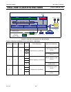
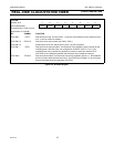
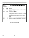
Table 7-2: Power Reduction Modes
PMOD1
(PCON.1)
PMOD0
(PCON.0)
Description
0 0 Normal Mode (Default) - no power reduction.
01
Idle Mode. The Idle mode leaves peripherals running in order to allow them to activate the processor
when an interrupt is generated. Any enabled interrupt source or reset may terminate Idle mode.
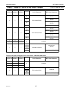
10
Power down mode:
The Power down mode stops the oscillator in order to minimize power consumption.
The P89LPC906/907/908 exits Power down mode via any reset, or certain interrupts - brownout
Interrupt, keyboard, Real-time clock (system timer), watchdog, and comparator trips. Waking up by reset
is only enabled if the corresponding reset is enabled, and waking up by interrupt is only enabled if the
corresponding interrupt is enabled and the EA SFR bit (IEN0.7) is set.
In Power down mode the internal RC oscillator is disabled unless both the RC oscillator has been
selected as the system clock AND the RTC is enabled
In Power down mode, the power supply voltage may be reduced to the RAM keep-alive voltage V
RAM
.
This retains the RAM contents at the point where Power down mode was entered. SFR contents are not
guaranteed after V
DD
has been lowered to V
RAM
, therefore it is recommended to wake up the processor
via Reset in this situation. V
DD
must be raised to within the operating range before the Power down mode
is exited.
When the processor wakes up from Power down mode, it will start the oscillator immediately and begin
execution when the oscillator is stable. Oscillator stability is determined by counting 1024 CPU clocks
after start-up when one of the crystal oscillator configurations is used, or 256 clocks after start-up for the
internal RC or external clock input configurations.
Some chip functions continue to operate and draw power during Power down mode, increasing the total
power used during Power down. These include:
• Brownout Detect
• Watchdog Timer if WDCLK (WDCON.0) is ’1’.
• Comparator (Note: Comparator can be powered down separately with PCONA.5 set to ’1’ and
comparator disabled);
• Real-time Clock/System Timer (and the crystal oscillator circuitry if this block is using it, unless
RTCPD, i.e., PCONA.7 is ’1’).
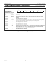
11
Total Power down mode: This is the same as Power down mode except that the Brownout Detection
circuitry and the voltage comparators are also disabled to conserve additional power. Note that a
brownout reset or interrupt will not occur. Voltage comparator interrupts and Brownout interrupt cannot
be used as a wakeup source.The internal RC oscillator is disabled unless both the RC oscillator has
been selected as the system clock AND the RTC is enabled.
The following are the wakeup options supported:
• Watchdog Timer if WDCLK (WDCON.0) is ’1’. Could generate Interrupt or Reset, either one can wake
up the device
• Keyboard Interrupt
• Real-time Clock/System Timer (and the crystal oscillator circuitry if this block is using it, unless
RTCPD, i.e., PCONA.7 is ’1’).
• Note: Using the internal RC-oscillator to clock the RTC during Power down may result in relatively high
power consumption. Lower power consumption can be achieved by using an external low frequency
clock when the Real-time Clock is running during Power down.