


Philips Semiconductors
User’s Manual - Preliminary -
P89LPC906/907/908
RESET
2003 Dec 8 72
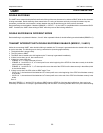
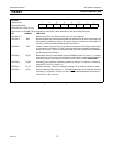
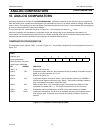
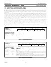
Figure 9-2: Reset Sources Register
RSTSRC
Address: DFH
Not bit addressable
Reset Sources: Power-on only
Reset Value: xx110000B (This is the power-on reset value. Other reset sources will set corresponding bits.)
BIT SYMBOL FUNCTION
RSTSRC.7-6 - Reserved for future use. Should not be set to 1 by user programs.
RSTSRC.5 BOF Brownout Detect Flag. When Brownout Detect is activated, this bit is set. It will remain set
until cleared by software by writing a ’0’ to the bit. (Note: On a Power-on reset, both POF
and this bit will be set while the other flag bits are cleared.)
RSTSRC.4 POF Power-on Detect Flag. When Power-on Detect is activated, the POF flag is set to indicate
an initial power-up condition. The POF flag will remain set until cleared by software by
writing a ’0’ to the bit.. (Note: On a Power-on reset, both BOF and this bit will be set while
the other flag bits are cleared.)
RSTSRC.3 R_BK Break detect reset. If a break detect occurs and EBRR (AUXR1.6) is set to ’1’, a system
reset will occur. This bit is set to indicate that the system reset is caused by a break detect.
Cleared by software by writing a ’0’ to the bit or on a Power-on reset. (P89LPC908)
RSTSRC.2 R_WD Watchdog Timer reset flag. Cleared by software by writing a ’0’ to the bit or a Power-on
reset.(NOTE: UCFG1.7 must be = 1).
RSTSRC.1 R_SF Software reset Flag. Cleared by software by writing a ’0’ to the bit or a Power-on reset.
RSTSRC.0 R_EX External reset Flag. When this bit is ’1’, it indicates external pin reset. Cleared by software
by writing a ’0’ to the bit or a Power-on reset. If RST
is still asserted after the Power-on
reset is over, R_EX will be set.
76543210
- - BOF POF R_BK R_WD R_SF R_EX