


Philips Semiconductors
User’s Manual - Preliminary -
P89LPC906/907/908
FLASH PROGRAM MEMORY
2003 Dec 8 92
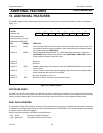
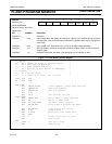
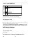
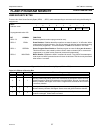
Figure 14-2: Assembly language routine to erase/program all or part of a page
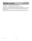
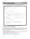
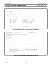
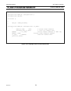
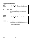
Figure 14-3: C-language routine to erase/program all or part of a page
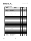
ACCESSING ADDITIONAL FLASH ELEMENTS
In addition to the user code array, the user’s firmware may access additional flash elements. These include UCFG1, the Boot
Vector, Status Bit, and signature bytes. Access of these elements uses a slightly different method than that used to access the
user code memory. Signature bytes are read-only. Security bytes may be erased only under certain conditions.
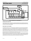
IAP-Lite is performed in the application under the control of the microcontroller’s firmware using four SFRs to facilitate erasing,
programming, or reading. These SFRs are:
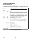
• FMCON (Flash Control Register). When read, this is the status register. When written, this is a command register. Note that
the status bits are cleared to ’0’s when the command is written.
• FMDATA (Flash Data Register). Accepts data to be loaded into or from the flash element.
• FMADRL (Flash memory address low). Used to specify the flash element.
The flash elements that may be accessed and their addresses are shown in Table 14-1.
unsigned char idata dbytes[16]; // data buffer
unsigned char Fm_stat; // status result
bit PGM_USER (unsigned char, unsigned char);
bit prog_fail;
void main ()
{
prog_fail=PGM_USER(0x1F,0xC0);
}
bit PGM_USER (unsigned char page_hi, unsigned char page_lo)
{
#define LOAD 0x00 // clear page register, enable loading
#define EP 0x68 // erase & program page
unsigned char i; // loop count
FMCON = LOAD; //load command, clears page reg
FMADRH = page_hi; //
FMADRL = page_lo; //write my page address to addr regs
for (i=0;i<16;i=i+1)
{
FMDATA = dbytes[i];
}
FMCON = EP; //erase & prog page command
Fm_stat = FMCON; //read the result status
if ((Fm_stat & 0x0F)!=0) prog_fail=1; else prog_fail=0;
return(prog_fail);
}