


Philips Semiconductors
User’s Manual - Preliminary -
P89LPC906/907/908
I/O PORTS
2003 Dec 8 37
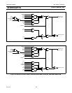
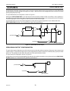
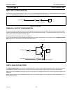
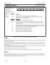
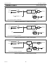
INPUT-ONLY CONFIGURATION
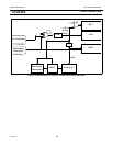
The input port configuration is shown in Figure 4-3. It is a Schmitt-triggered input that also has a glitch suppression circuit (please
refer to the P89LPC906/907/908 datasheet, AC Characteristics for glitch filter specifications)
Figure 4-3: Input Only
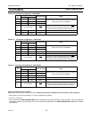
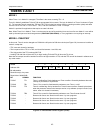
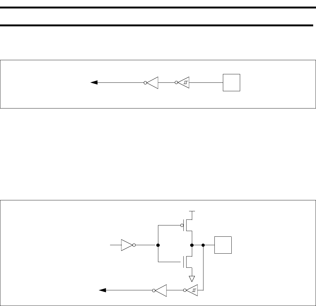
PUSH-PULL OUTPUT CONFIGURATION
The push-pull output configuration has the same pulldown structure as both the open drain and the quasi-bidirectional output
modes, but provides a continuous strong pullup when the port latch contains a logic 1. The push-pull mode may be used when
more source current is needed from a port output.
The push-pull port configuration is shown in Figure 4-4.
A push-pull port pin has a Schmitt-triggered input that also has a glitch suppression circuit (please refer to the P89LPC906/907/
908 datasheet, AC Characteristics for glitch filter specifications)
Figure 4-4: Push-Pull Output
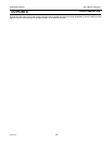
PORT 0 ANALOG FUNCTIONS
The P89LPC906/907/908 incorporates an analog comparator. In order to give the best analog performance and minimize power
consumption, pins that are being used for analog functions must have both the digital outputs and digital inputs disabled.
Digital outputs are disabled by putting the port pins into the input-only mode as described in the Port Configurations section (see
Table 4-2).
Digital inputs on Port 0 may be disabled through the use of the PT0AD register. On any reset, the PT0AD bits default to ’0’s to
enable digital functions.
port
pin
input data
glitch rejection
strong
V
DD
input data
port latch data
port
pin
glitch rejection