


Philips Semiconductors
User’s Manual - Preliminary -
P89LPC906/907/908
UART
2003 Dec 8 60
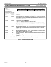
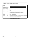
SFR SPACE
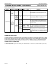
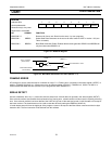
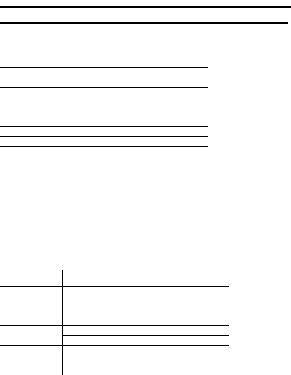
The UART SFRs are at the following locations:
Table 8-1: SFR Locations for UARTs
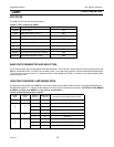
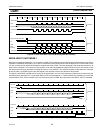
BAUD RATE GENERATOR AND SELECTION
The enhanced UART has an independent Baud Rate Generator. The baud rate is determined by a value programmed into the
BRGR1 and BRGR0 SFRs. The UART can use either Timer 1 or the baud rate generator output as determined by BRGCON.2-
1 (see Figure 8-2). Note that Timer T1 is further divided by 2 if the SMOD1 bit (PCON.7) is cleared. The independent Baud Rate
Generator uses CCLK.
UPDATING THE BRGR1 AND BRGR0 SFRS
The baud rate SFRs, BRGR1 and BRGR0 must only be loaded when the Baud Rate Generator is disabled (the BRGEN bit in
the BRGCON register is ’0’). This avoids the loading of an interim value to the baud rate generator. (CAUTION: If either BRGR0
or BRGR1 is written when BRGEN = 1, the result is unpredictable.)
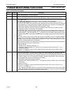
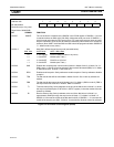
Table 8-2: Baud Rate Generation for UART
Register Description SFR Location
PCON Power Control 87H
SCON Serial Port (UART) Control 98H
SBUF Serial Port (UART) Data Buffer 99H
SADDR Serial Port (UART) Address A9H
SADEN Serial Port (UART) Address Enable B9H
SSTAT Serial Port (UART) Status BAH
BRGR1 Baud Rate Generator Rate High Byte BFH
BRGR0 Baud Rate Generator Rate Low Byte BEH
BRGCON Baud Rate Generator Control BDH
SCON.7
(SM0)
SCON.6
(SM1)
PCON.7
(SMOD1)
BRGCON.1
(SBRGS)
Receive/Transmit Baud Rate for UART
0 0 X X CCLK/16
01
0 0 CCLK/(256-TH1)64
1 0 CCLK/(256-TH1)32
X 1 CCLK/((BRGR1,BRGR0)+16)
10
0 X CCLK/32
1 X CCLK/16
11
0 0 CCLK/(256-TH1)64
1 0 CCLK/(256-TH1)32
X 1 CCLK/((BRGR1,BRGR0)+16)