


Philips Semiconductors
User’s Manual - Preliminary -
P89LPC906/907/908
UART
2003 Dec 8 68
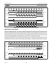
- If DBISEL is ’1’ and INTLO is ’1’, a Tx interrupt will occur at the end of the STOP bit of the data currently in the shifter (which
is also the last data).
7. If there is more data, the CPU writes to TB8 again.
8. The CPU writes to SBUF again. Then:
- If INTLO is ’0’, the new data will be loaded and a Tx interrupt will occur at the beginning of the STOP bit of the data currently
in the shifter.
- If INTLO is ’1’, the new data will be loaded and a Tx interrupt will occur at the end of the STOP bit of the data currently in the
shifter.
Go to 4.
Note that if DBISEL is ’1’ and the CPU is writing to SBUF when the STOP bit of the last data is shifted out, there can be an
uncertainty of whether a Tx interrupt is generated already with the UART not knowing whether there is any more data
following.
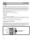
MULTIPROCESSOR COMMUNICATIONS
UART modes 2 and 3 have a special provision for multiprocessor communications. In these modes, 9 data bits are received or
transmitted. When data is received, the 9th bit is stored in RB8. The UART can be programmed such that when the stop bit is
received, the serial port interrupt will be activated only if RB8 = 1. This feature is enabled by setting bit SM2 in SCON. One way
to use this feature in multiprocessor systems is as follows:
When the master processor wants to transmit a block of data to one of several slaves, it first sends out an address byte which
identifies the target slave. An address byte differs from a data byte in that the 9th bit is 1 in an address byte and 0 in a data byte.
With SM2 = 1, no slave will be interrupted by a data byte. An address byte, however, will interrupt all slaves, so that each slave
can examine the received byte and see if it is being addressed. The addressed slave will clear its SM2 bit and prepare to receive
the data bytes that follow. The slaves that weren’t being addressed leave their SM2 bits set and go on about their business,
ignoring the subsequent data bytes.
Note that SM2 has no effect in Mode 0, and must be ’0’ in Mode 1.
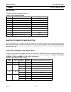
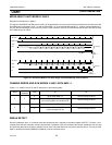
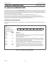
AUTOMATIC ADDRESS RECOGNITION
Automatic Address Recognition is a feature which allows the UART to recognize certain addresses in the serial bit stream by
using hardware to make the comparisons. This feature saves a great deal of software overhead by eliminating the need for the
software to examine every serial address which passes by the serial port. This feature is enabled by setting the SM2 bit in SCON.
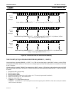
In the 9 bit UART modes (mode 2 and mode 3), the Receive Interrupt flag (RI) will be automatically set when the received byte
contains either the “Given” address or the “Broadcast” address. The 9 bit mode requires that the 9th information bit is a 1 to
indicate that the received information is an address and not data.
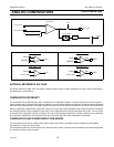
Using the Automatic Address Recognition feature allows a master to selectively communicate with one or more slaves by
invoking the Given slave address or addresses. All of the slaves may be contacted by using the Broadcast address. Two special
Function Registers are used to define the slave’s address, SADDR, and the address mask, SADEN. SADEN is used to define
which bits in the SADDR are to be used and which bits are “don’t care”. The SADEN mask can be logically ANDed with the
SADDR to create the “Given” address which the master will use for addressing each of the slaves. Use of the Given address
allows multiple slaves to be recognized while excluding others. The following examples will help to show the versatility of this
scheme:
Slave 0 SADDR = 1100 0000
SADEN = 1111 1101
Given = 1100 00X0
Slave 1 SADDR = 1100 0000
SADEN = 1111 1110
Given = 1100 000X
In the above example SADDR is the same and the SADEN data is used to differentiate between the two slaves. Slave 0 requires
a 0 in bit 0 and it ignores bit 1. Slave 1 requires a 0 in bit 1 and bit 0 is ignored. A unique address for Slave 0 would be 1100 0010