


Philips Semiconductors Product specification
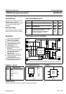
TOPFET dual high side switch PIP3207-DC
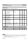
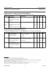
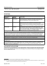
LIMITING VALUES
Limiting values in accordance with the Absolute Maximum System (IEC 134)
SYMBOL PARAMETER CONDITIONS MIN. MAX. UNIT
V
BG
Continuous supply voltage 0 50 V
I
L
Continuous load current per channel T
mb
≤
135˚C - 8 A
P
D
Total power dissipation T
mb
≤
25˚C - 83.3 W
T
stg
Storage temperature -55 175 ˚C
T
j
Continuous junction temperature
1
-40 150 ˚C
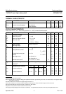
Reverse battery voltages
2
V
GB
Continuous reverse voltage - 16 V
V
GB
Peak reverse voltage - 32 V
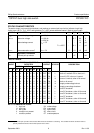
Application information
R
I
, R
S
External resistors
3
to limit input, status currents 3.2 - kΩ
Input and status currents
I
I
Continuous input current -5 5 mA
I
S
Continuous status current -5 5 mA
I
I
Repetitive peak input current δ ≤ 0.1, t
p
= 300 µs -50 50 mA
I
S
Repetitive peak status current δ ≤ 0.1, t
p
= 300 µs -50 50 mA
Inductive load clamping V
BG
= 13 V, I
L
= 8 A
E
BL
Non-repetitive clamping energy (one T
j
= 150˚C prior to turn-off - 150 mJ
channel)
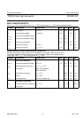
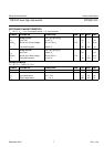
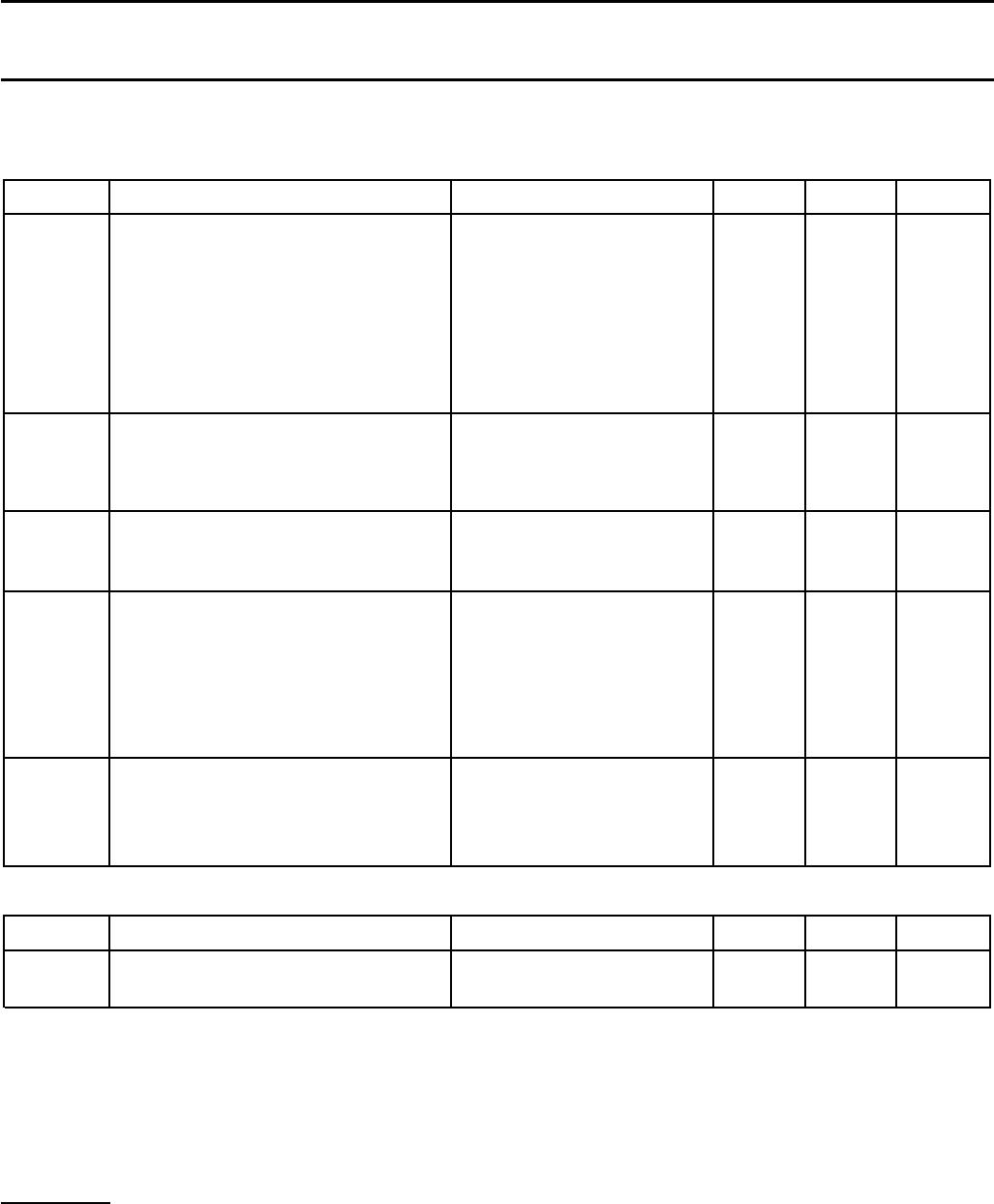
ESD LIMITING VALUE
SYMBOL PARAMETER CONDITIONS MIN. MAX. UNIT
V
C
Electrostatic discharge capacitor Human body model; - 2 kV
voltage C = 250 pF; R = 1.5 kΩ
1 For normal continuous operation. A higher T
j
is allowed as an overload condition but at the threshold T
j(TO)
the over temperature trip operates
to protect the switch.
2 Reverse battery voltage is allowed only with external resistors to ensure that the input and status currents do not exceed the limiting values.
The internal ground resistor limits the reverse battery ground current. The connected loads must limit the reverse load currents. Power
is dissipated and the T
j
rating must be observed.
3 To limit currents during reverse battery and transient overvoltages (positive or negative).
September 2001 2 Rev 1.100