


Controls and Connectors
11-30 Monitor Installation and Patient Safety
Monitor Installation
and Patient Safety
loudspeaker is not covered and can be heard. The most suitable
location for the External Alarm Device is in close proximity to the
ITE display.
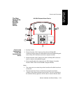
The Rear
Panel of the
M1026A
Anesthetic
Gas Module
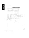
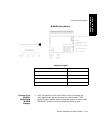
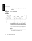
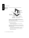
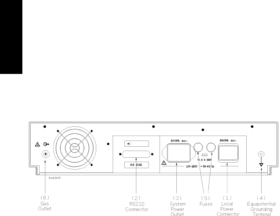
The connections on the rear panel of the Anesthetic Gas Module are
shown in the following diagram:
The rear of the Anesthetic Gas Module has the following connections:
1. Local Power connector; a 3-pin connector is used to input the local
line voltage.
2. RS232 Connector (RS232 Interface); a 25-pin “D” type connector is
used for connection to the ACMS.
Note—Do not apply a voltage greater than ±12V to the RS232
connections.
3. System Power Outlet (restricted use); this can be used to output
power to the Philips M1165A/66A/75A/76A ACMS.
MONITOR