


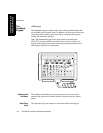
Parameter Modules
The CMS and V24 and V26 Patient Monitors 1-17
The CMS and V24 and
V26 Patient Monitors
special Service Mode, either by your biomedical engineering department
or the Philips service engineer. You can find a description of this behavior
(called “Parameter Settings Transfer”) in Chapter 3.
Symbols to
Indicate Key
Functions
As detailed in the table below, some modules used with the M1046A CMS,
and M1205A V24/26 patient monitors now use symbols, instead of words,
to indicate the function of some keys. If the monitor’s Reference Manual
tells you, for example, to select the START key, you should press the key
marked with the corresponding “start” symbol.
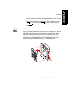
The design change also means that you will now find the module’s
product number (for example M1032A) on the rear of the module’s
housing, not on the front. Although the new modules do not show the
letter “T” on the housing, all modules retain their capability to transfer
parameter settings from one monitor to another.
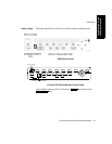
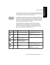
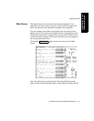
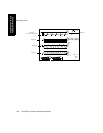
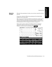
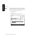
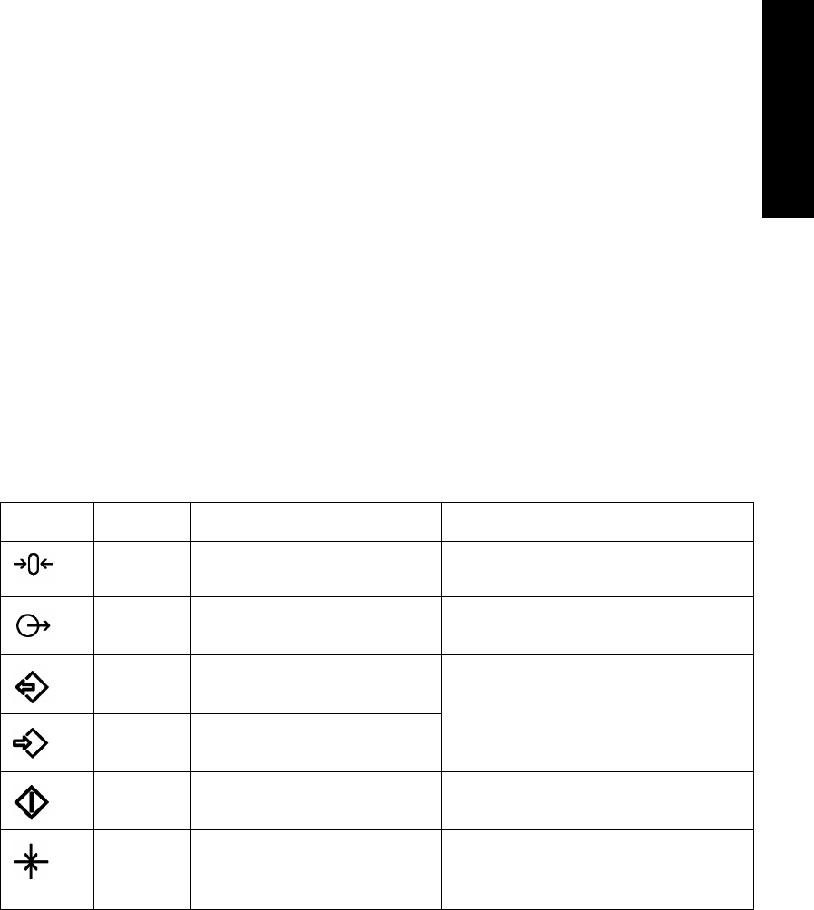
Symbol Name Function Which Modules?
ZERO zero a pressure transducer Pressure (M1006B), including
option C01
Press
Out
pressure outlet connector Pressure (M1006B) option C01
Monitor initiates transfer from
module to monitor
Data Transfer Module (M1235A)
Module initiates transfer from
monitor to module
START start measurement CCO/C.O. (M1012A)
CCO/C.O. including option C10
Cal calibrate SvO
2
(M1021A), tcpO
2
/tcpCO
2
(M1018A)
Mainstream CO
2
(M1016A)