


9 Go to cover page
15
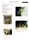
Mechanical Instructions
0. General
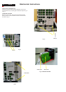
2. Video panel
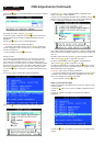
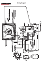
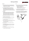
3.Main board connector in Fig. 4
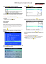
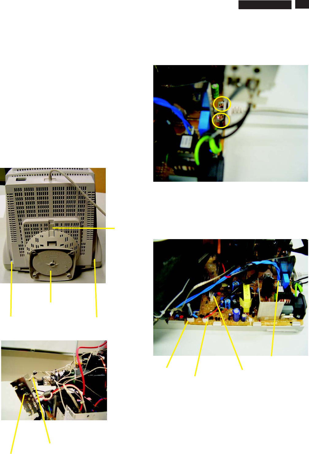
To be able to perform measurements and repairs on the "circuit
boards", these unit should placed in the service position first.
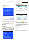
-Remove 2 screws as shown
-Remove back cover as shown
-Remove pedestal as shown
-Disconnect york wire
-Disconnect rotation connector
-Disconnect control board connector
-Remove Screw for fixed I/F cable
-Remove signal connector
-Remove degaussing wire connector
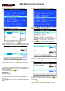
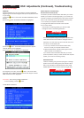
1.Remove the rear cover in Fig. 1.
- Disconnect the wire between metal shield of Video panel and
CRT neck as shown in Fig. 2.
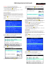
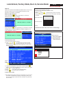
- Disconnect the CRT ground from Video panel.
- Remove screw grounding and grounding wire in Fig. 3.
Fig. 1
Screw
Screw
Pedestal ass'y
Video Panel
CRT grouding wirel
Fig. 2
Clip
Fig. 3
Fig. 4
screw - grounding
Control connector
Signal connector
Degaussing wire connector
Rotation connector
===============>
107T5