


X
Go to cover page
21
107T5
DDC Instructions
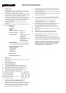
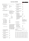
1. General
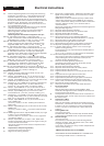
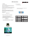
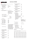
3. Pin assignment
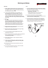
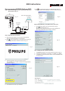
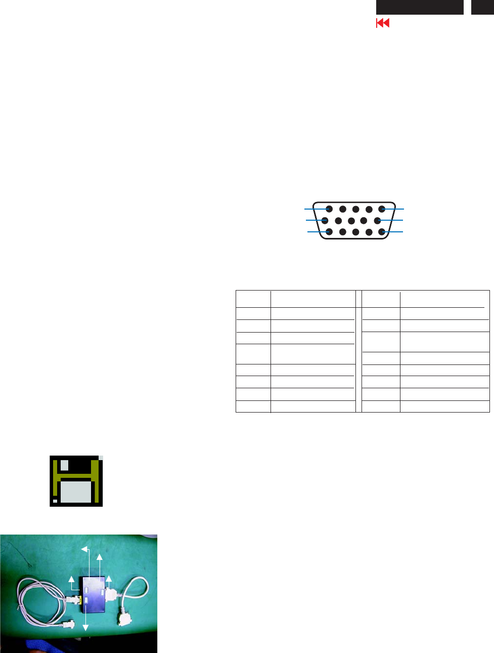
Fig. 2 Alignment Kits
To Monitor
DC 8V~12V
Video Card
Video Card
To Printer
Power indicator
A. 15-pin D-Sub Connector
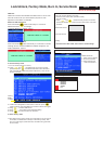
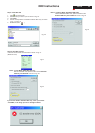
DDC Data Re-programming
In case the main EEPROM with which store all factory
settings were replaced because a defect,repaired monitor the serial
numbers have to be re-programmed.
It is advised to re-soldered the main EEPROM from
the old board onto the new board if circuit board have been replaced, in
this case the DDC data does not need to be re-programmed.
Additional information
Additional information about DDC (Display Data Channel) may be
obtained from Video Electronics Standards Association (VESA).
Extended Display Identification Data(EDID) information may be also
obtained from VESA.
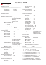
DDC EDID structure
For the monitor : Standard Version 3.0
Structure Version 1.2
1. An i486 (or above) personal computer or compatible.
2. Microsoft operation system Windows 95/98.
4. Software DDC Alignment kits (4822 310 11184) shown as Fig. 2.
The kit contents: a. Alignment box x1
b. Printer cable x1
c. D-Sub cable x1
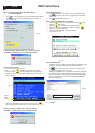
Note: The EDID301.EXE (Release Version 1.58, 20000818)is a
windows-based program, which cannot be run in MS-DOS.
Software DDC
with Software DDC
3. EDID301.EXE program (3138 106 10103) shown as Fig. 1
2. System and equipment requirements
Diskette with EDID301.EXE
EDID301.EXE
Figure 1
Ver:1.58
The 15-pin D-sub connector (male) of the signal cable
on the 3rd row for DDC feature :
1
10
6
11
15
5
Assignment
Assignment
Pin No.
Pin No.
Ground
Ground
Blue video input
2
7
6
8
4
5
3
1
9
12
11
14
13
15
10
Red video ground
Blue video ground
Green video ground
for selftest(PC ground)
Not connected - no.pin
Sync. Ground
Data clock line(SCL)
V.Sync(VCLK)
H.Sync
Bi-directional data(SDA)
Green video input
Red video input