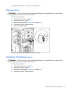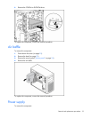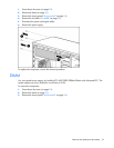
Removal and replacement procedures 36
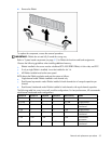
Channel A Channel A Channel B Channel B Total memory Mode
Slot 1 Slot 2 Slot 3 Slot 4
1 GB 1 GB 2 GB 2 GB 6 GB
Dual-channel
interleaved
2 GB 2 GB 2 GB 2 GB 8 GB
Dual-channel
interleaved
Processor assembly
IMPORTANT: To avoid damage to the processor and system board, only authorized technicians trained
by HP should attempt to replace or install the processor in this server.
To remove the component:
1. Power down the server (on page 25).
2. Remove the bezel (on page 25).
3. Remove the access panel ("Access panel" on page 26).
4. Remove the air baffle ("Air baffle" on page 33).
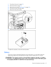
5. Disconnect the fan cable from the system board.
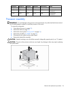
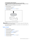
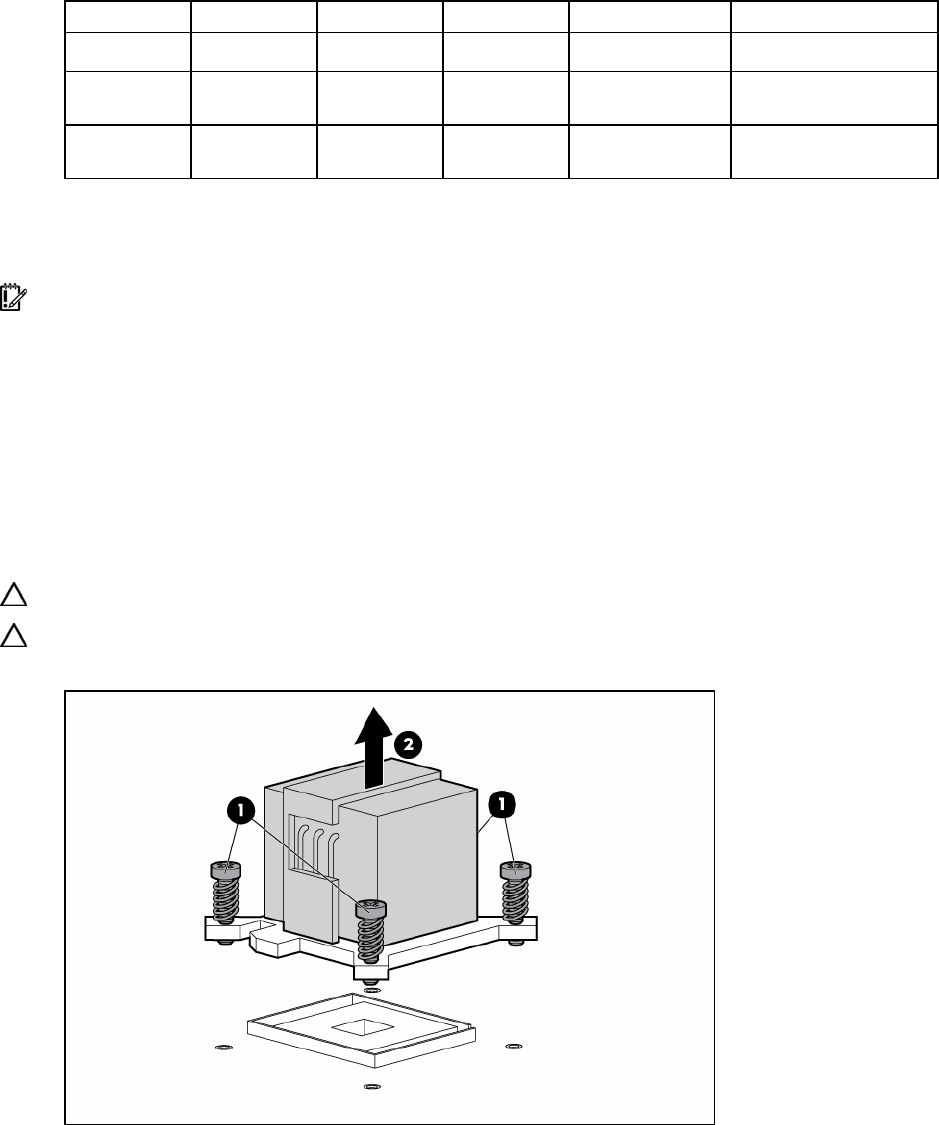
6. Remove the heatsink fan assembly.
CAUTION: Heatsink retaining screws should be removed in diagonally opposite pairs (in an "X" pattern).
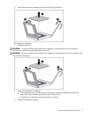
CAUTION: The pins on the processor socket are very fragile. Any damage to them may require replacing
the system board.


