


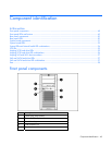
Component identification 51
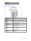
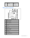
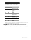
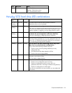
Item Description Status
1 NIC link LED On = Link
Off = No link
2 NIC activity LED Flashing = Activity
Off = No activity
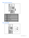
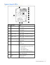
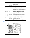
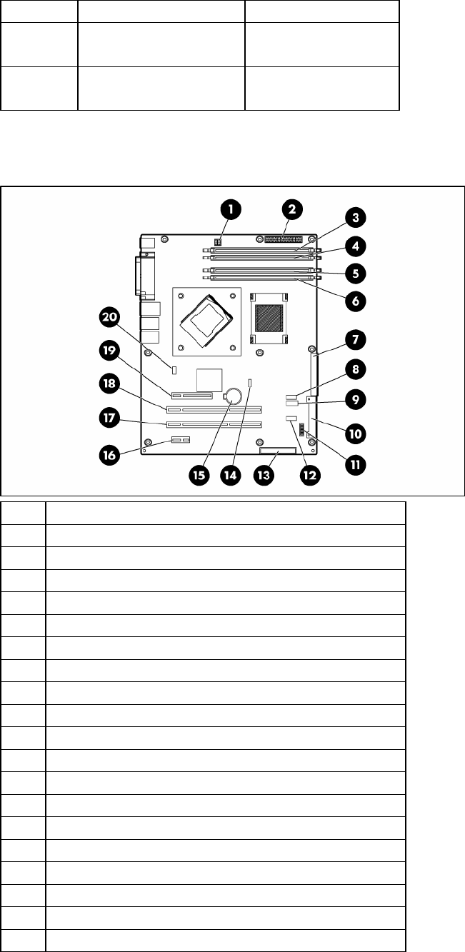
System board components
Items Description
1 Processor power connector
2 System power connector
3 DIMM slot 4 (Channel B)
4 DIMM slot 3 (Channel B)
5 DIMM slot 2 (Channel A)
6 DIMM slot 1 (Channel A)
7 IDE connector
8 Front USB connector
9 USB connector
10 SATA connector
11 System maintenance switch
12 USB tape drive connector
13 Diskette drive connector
14 Processor fan connector
15 System battery
16 Slot 1, PCI Express x1
17 Slot 2, 64-bit/100-MHz PCI-X
18 Slot 3, 64-bit/100-MHz PCI-X
19 Slot 4, PCI Express x4*