ANSI X3.64 Emulation
37
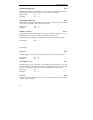
Set Perforation Skip ESC N n
Sets the perforation skip distance to n lines at the current line spacing. 1≥n≥255. If line spacing is changed
after setting the skip distance, the skip distance will not be changed.
The skip distance is split between the top and bottom margins, so the perforation will be centered in the
resulting white space. The specified skip distance must be less than the form length, or the command will be
ignored. Perforation skip is canceled by ESC O, ESC C n or ESC C NUL n. Overrides the “Top Margin”
and “Bottom Margin” values in the forms menu.
Example: The following escape sequence will set a two inch perforation skip distance, if the current line
spacing is 6 lpi. This will result in a one inch top and bottom margin.
Escape Sequence: ESC N 12
Hexadecimal: 1B 4E 0C
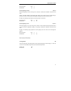
Cancel Perforation Skip ESC O
Cancels perforation skip. This is equivalent to having no top and bottom margin. Overrides the “Top
Margin” and “Bottom Margin” values in the forms menu.
Escape Sequence: ESC O
Hexadecimal: 1B 4F
Graphics
Graphics mode gives the user complete control over every dot position on the paper. Graphics may be
printed with various horizontal densities from 60 to 240 dpi, and a vertical density of 72 dpi.
Each byte of graphics data represents a vertical column of eight dots, with the MSB (most significant bit)
corresponding to the top wire of the print head. Turning a bit on causes a dot to be printed. The bit values
corresponding to each wire of the print head are shown below:
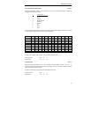
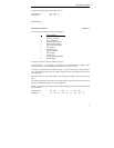
wire 1 128 (80 hex)
wire 2 64 (40 hex)
wire 3 32 (20 hex)
wire 4 16 (10 hex)
wire 5 8 (08 hex)
wire 6 4 (04 hex)
wire 7 2 (02 hex)
wire 8 1 (01 hex)
The appropriate bit values are added together to fire the desired wires. For example, a byte of graphics data
with the value 128 (80 hex) will fire the top wire, wire 1. A value of 192 (C0 hex) will fire the top two wires,
wires 1 and 2. A value of 11 (0B hex) will fire wires 5, 7 and 8.
Each graphics sequence contains two bytes (n1 and n2) that specify how many bytes of graphics data follow.
The first byte, n1, can specify values up to 255. If that is sufficient, then n2 is set to zero. For values greater
than 255, n2 comes into play. The n2 byte specifies multiples of 256. For example, to specify 520 bytes of
graphics data, n1 = 8 and n2 = 2. The bytes of graphics data are strung together to create a graphics line


