


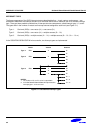
S3C8275X/F8275X/C8278X/F8278X/C8274X/F8274X INTERRUPT STRUCTURE
5-3
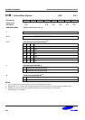
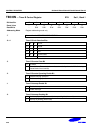
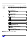
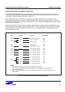
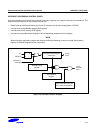
S3C8275X/C8278X/C8274X INTERRUPT STRUCTURE
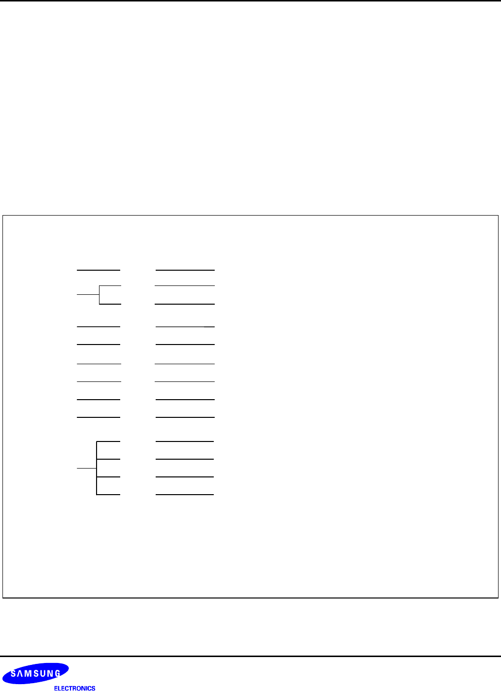
The S3C8275X/C8278X/C8274X microcontroller supports twelve interrupt sources. All twelve of the interrupt
sources have a corresponding interrupt vector address. Eight interrupt levels are recognized by the CPU in this
device-specific interrupt structure, as shown in Figure 5-2.
When multiple interrupt levels are active, the interrupt priority register (IPR) determines the order in which
contending interrupts are to be serviced. If multiple interrupts occur within the same interrupt level, the interrupt
with the lowest vector address is usually processed first (The relative priorities of multiple interrupts within a single
level are fixed in hardware).
When the CPU grants an interrupt request, interrupt processing starts. All other interrupts are disabled and the
program counter value and status flags are pushed to stack. The starting address of the service routine is fetched
from the appropriate vector address (plus the next 8-bit value to concatenate the full 16-bit address) and the
service routine is executed.
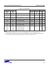
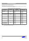
Vectors SourcesLevels Reset/Clear
NOTES:
1. Within a given interrupt level, the low vector address has high priority.
For example, F0H has higher priority than F2H within the level IRQ0 the priorities within each
level are set at the factory.
2. External interrupts are triggered by a rising or falling edge, depending on the corresponding control
register setting.
IRQ3 E0H P0.0 external interrupt
E2H P0.1 external interrupt
SIO interrupt
F4H
Watch timer overflow
F6H
IRQ1
IRQ2
S/W
P0.2 external interrupt
E4H
P1.3 external interrupt
E6H
IRQ4
IRQ5
P1.7 external interrupt
P1.6 external interrupt
P1.5 external interrupt
P1.4 external interrupt
IRQ6
EEH
ECH
EAH
E8H
Timer B match
IRQ0
F0H Timer 1/A match
S/W
S/W
S/W
S/W
S/W
S/W
S/W
S/W
S/W
S/W
S/W
Basic timer overflow
100H
RESET
H/W
IRQ7
F2H
Figure 5-2. S3C8275X/C8278X/C8274X Interrupt Structure