


INTERRUPT STRUCTURE S3C8275X/F8275X/C8278X/F8278X/C8274X/F8274X
5-16
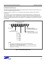
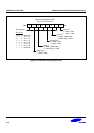
GENERATING INTERRUPT VECTOR ADDRESSES
The interrupt vector area in the ROM (00H−FFH) contains the addresses of interrupt service routines that
correspond to each level in the interrupt structure. Vectored interrupt processing follows this sequence:
1. Push the program counter's low-byte value to the stack.
2. Push the program counter's high-byte value to the stack.
3. Push the FLAG register values to the stack.
4. Fetch the service routine's high-byte address from the vector location.
5. Fetch the service routine's low-byte address from the vector location.
6. Branch to the service routine specified by the concatenated 16-bit vector address.
NOTE
A 16-bit vector address always begins at an even-numbered ROM address within the range of 00H−FFH.
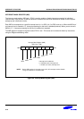
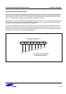
NESTING OF VECTORED INTERRUPTS
It is possible to nest a higher-priority interrupt request while a lower-priority request is being serviced. To do this,
you must follow these steps:
1. Push the current 8-bit interrupt mask register (IMR) value to the stack (PUSH IMR).
2. Load the IMR register with a new mask value that enables only the higher priority interrupt.
3. Execute an EI instruction to enable interrupt processing (a higher priority interrupt will be processed if it
occurs).
4. When the lower-priority interrupt service routine ends, restore the IMR to its original value by returning the
previous mask value from the stack (POP IMR).
5. Execute an IRET.
Depending on the application, you may be able to simplify the procedure above to some extent.
INSTRUCTION POINTER (IP)
The instruction pointer (IP) is adopted by all the S3C8-series microcontrollers to control the optional high-speed
interrupt processing feature called fast interrupts. The IP consists of register pair DAH and DBH. The names of IP
registers are IPH (high byte, IP15−IP8) and IPL (low byte, IP7−IP0).
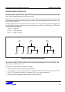
FAST INTERRUPT PROCESSING
The feature called fast interrupt processing allows an interrupt within a given level to be completed in
approximately 6 clock cycles rather than the usual 16 clock cycles. To select a specific interrupt level for fast
interrupt processing, you write the appropriate 3-bit value to SYM.4−SYM.2. Then, to enable fast interrupt
processing for the selected level, you set SYM.1 to “1”.