


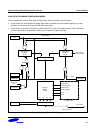
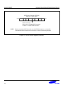

S3C8275X/F8275X/C8278X/F8278X/C8274X/F8274X CLOCK CIRCUIT
7-3
CLOCK STATUS DURING POWER-DOWN MODES
The two power-down modes, Stop mode and Idle mode, affect the system clock as follows:
• In stop mode, the main oscillator is halted. Stop mode is released, and the oscillator started, by a reset
operation or an external interrupt (with RC delay noise filter).
• In Idle mode, the internal clock signal is gated to the CPU, but not to interrupt structure, timers and timer/
counters. Idle mode is released by a reset or by an external or internal interrupt.
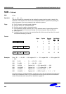
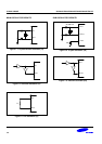
CPU Clock
IDLE Instruction
Selector 2CLKCON.4-.3
System Clock
1/1-1/4096
Frequency
Dividing
Circuit
Stop Release
Main-System
Oscillator
Circuit
Selector 1
f
x
f
xt
Stop
Sub-system
Oscillator
Circuit
INT
OSCCON.0
OSCCON.3
OSCCON.2
STPCON
STOP OSC
inst.
f
XX
Stop
Basic Timer
Timer/Counters
Watch Timer
1/1 1/161/2 1/8
LCD Controller
SIO
BLD
Watch Timer
LCD Controller
Figure 7-6. System Clock Circuit Diagram